Central tubular structure of a shaft seat and fan device thereof

a technology of central tubular structure and fan device, which is applied in the direction of positive displacement liquid engine, piston pump, liquid fuel engine, etc., can solve the problems of difficult deployment of the control circuit of the fan device, limited space for the layout of the control circuit, and burnout of electronic components

Active Publication Date: 2014-02-18
ASIA VITAL COMPONENTS SHENZHEN CO LTD
View PDF13 Cites 11 Cited by
  • Summary
  • Abstract
  • Description
  • Claims
  • Application Information

AI Technical Summary

Benefits of technology

[0011]The substrate board can be assembled with the shaft seat without any perforation. Therefore, the layout of the circuits on the substrate board is facilitated and the working time is greatly shortened to lower the manufacturing cost. According to the aforesaid, the present invention has the following advantages:
[0013]2. The manufacturing cost of the present invention is lowered.

Problems solved by technology

Otherwise, the temperature will rise very quickly to cause burnout of the electronic components.
As a result, the space for the layout of the control circuits is limited and it is hard to deploy the control circuits of the fan device.
Moreover, a large amount of material of the substrate board is wasted.
According to the aforesaid, the conventional fan device has the following defects:1. It is hard to deploy the circuits.2. The space for the layout of the circuits is limited.3. A large amount of material is wasted.

Method used


Image

  • Central tubular structure of a shaft seat and fan device thereof
  • Central tubular structure of a shaft seat and fan device thereof
  • Central tubular structure of a shaft seat and fan device thereof

Examples


Embodiment Construction

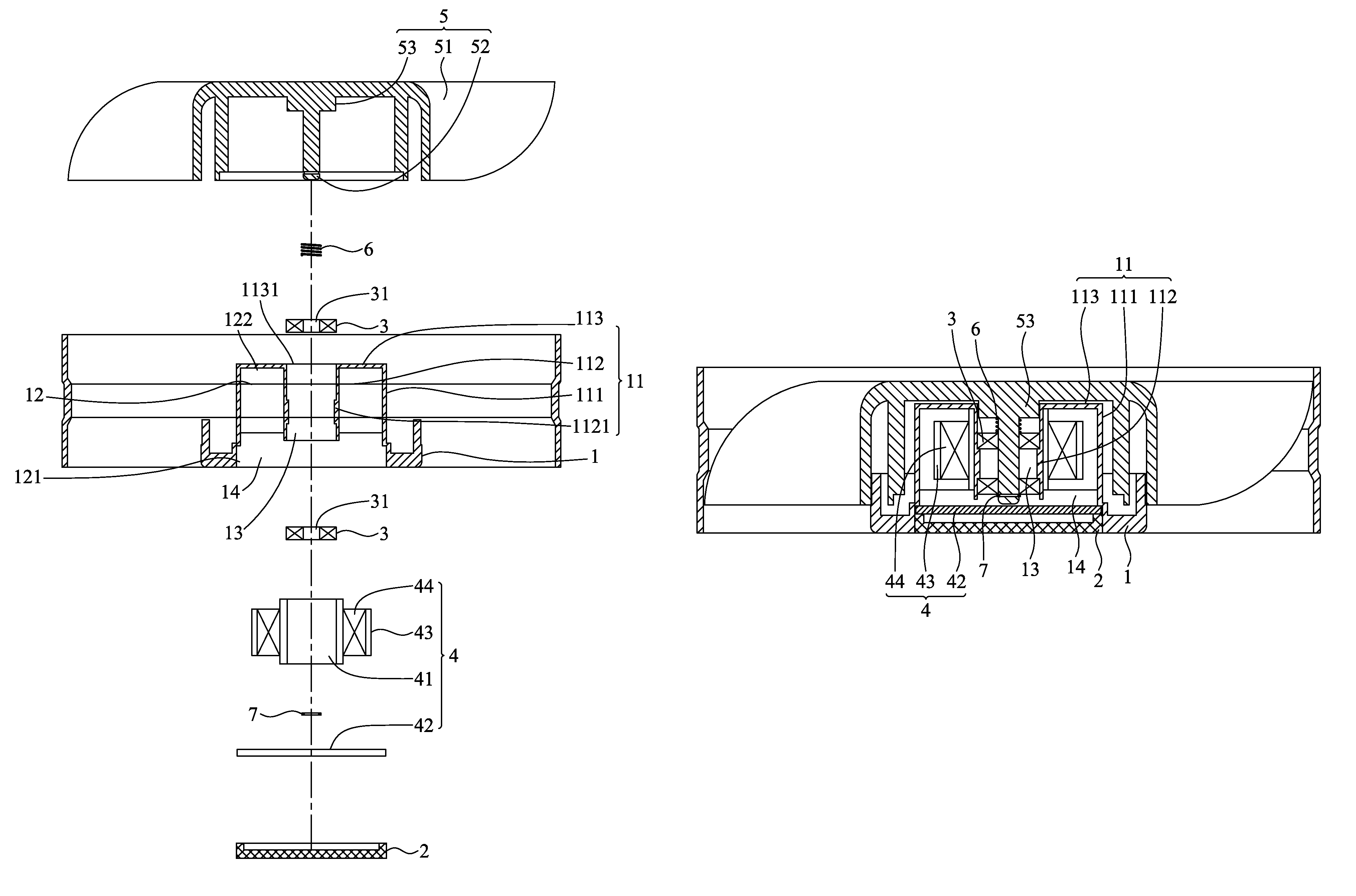
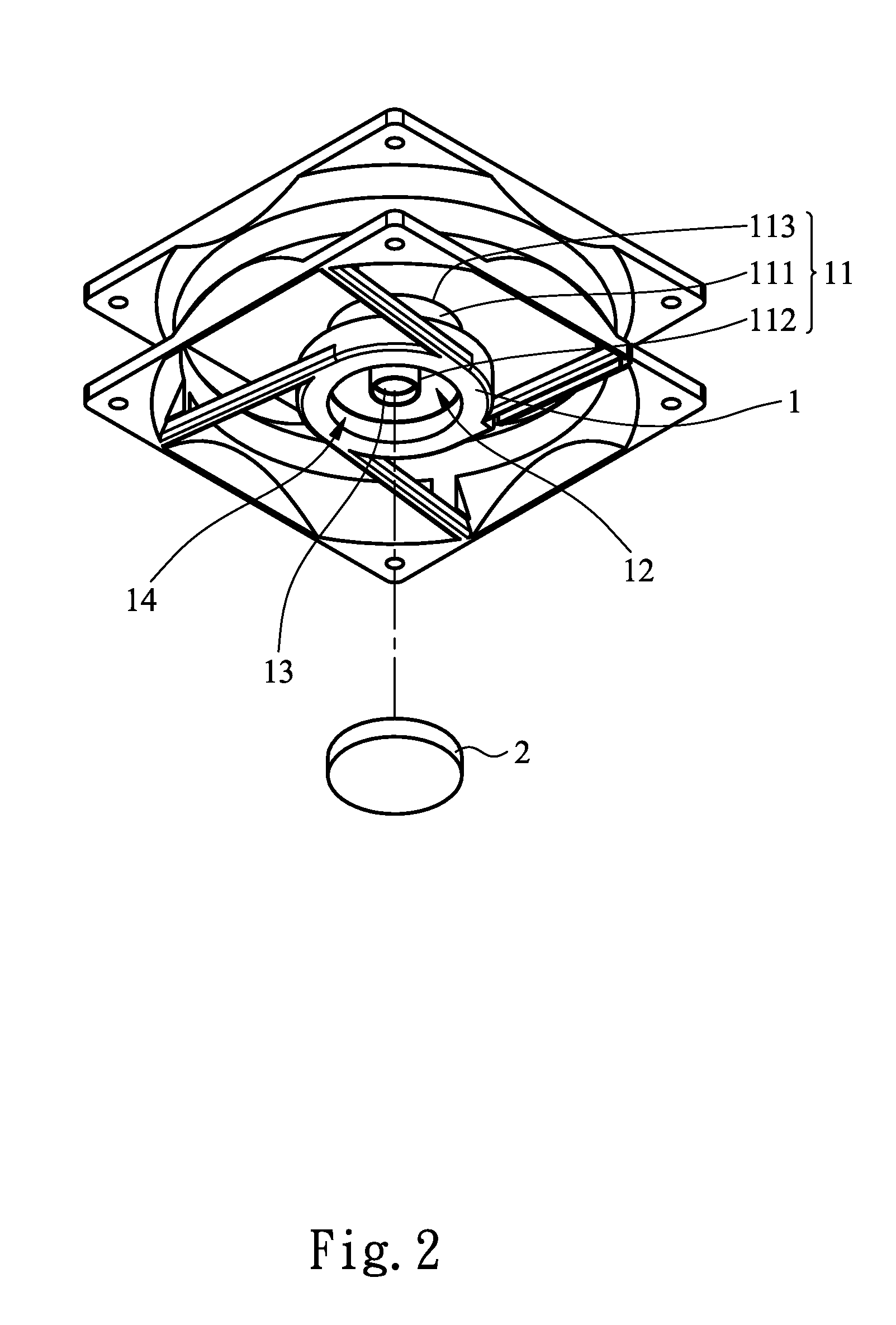
[0024]Please refer to FIGS. 2, 3 and 4. The central tubular structure of the shaft seat of the present invention is applied to a fan device. The central tubular structure of the shaft seat includes a base 1, a bushing 11 and a sealing member 2. The bushing 11 is connected with the base 1, having an outer tubular wall 111, an inner tubular wall 112 and a top section 113. The top section 113 is interconnected between the outer and inner tubular walls 111, 112 to together define a receiving space 12. The inner tubular wall 112 defines therein a bearing hole 13 having an open end 1131 in adjacency to the top section 113. The bushing 11 further has a reception space 14 in adjacency to the base 1. The reception space 14 has a first end opposite to the top section 113 in communication with the receiving space 12 and the bearing hole 13. The reception section 14 further has a second end in adjacency to the base 1. The sealing member 2 is fitted in the reception space 14 to seal the second e...


PUM


Abstract

A central tubular structure of a shaft seat and a fan device thereof. The central tubular structure includes a base, a bushing connected with the base and a sealing member. The bushing has an outer tubular wall, an inner tubular wall and a top section interconnected between the outer and inner tubular walls to define a receiving space. The inner tubular wall defines a bearing hole. The bushing further has a reception space in adjacency to the base in communication with the receiving space and the bearing hole. The sealing member is fitted in the reception space to seal the same. The fan device is composed of the central tubular structure, a stator assembly, at least one bearing and a fan propeller. The stator assembly is arranged in the receiving space and has a substrate board. The substrate board is free from any perforation and received in the reception space.

Description

FIELD OF THE INVENTION[0001]The present invention relates to a central tubular structure of a shaft seat and a fan device thereof, and more particularly to a central tubular structure of a shaft seat, in which the substrate board can be assembled with the shaft seat without any perforation. Therefore, the layout of the circuits on the substrate board is facilitated and the working time is greatly shortened to lower the manufacturing cost.BACKGROUND OF THE INVENTION[0002]Following the rapid development of various 3C products, the performances of all kinds of electronic components of the 3C products have been rapidly promoted to have faster and faster processing speed. The electronic components work at high speed and generate high heat at the same time. The heat must be efficiently dissipated outward. Otherwise, the temperature will rise very quickly to cause burnout of the electronic components. In order to avoid damage of the electronic components, in general, at least one heat diss...

Claims


Application Information

Patent Timeline
Patent Type & Authority Patents(United States)
IPC IPC(8): F04D29/05
CPCF04D29/083F04D25/062F04D25/068
Inventor SHEN, CHING-HANG
Owner ASIA VITAL COMPONENTS SHENZHEN CO LTD
Why Eureka
Try Eureka