
Keyswitch device, supporting seat and key cap thereof

a keyswitch and key cap technology, applied in the field of keyswitch devices, can solve the problems of unfavorable high manufacturing cost, and unfavorable high manufacturing cost, and achieve the effect of low manufacturing cost and small heigh

Active Publication Date: 2014-02-18
WISTRON CORP
View PDF8 Cites 5 Cited by
  • Summary
  • Abstract
  • Description
  • Claims
  • Application Information

AI Technical Summary

Benefits of technology

[0009]Therefore, the object of the present invention is to provide a keyswitch device that has a relatively simple structure with a required strength and a relatively low manufacturing cost, and to provide an assembly comprising a supporting seat and a key cap of the abovementioned keyswitch device.
[0016]The effect of this invention is that since the keyswitch device utilizes a new configuration, and since the supporting seat is made of metal by stamping, the keyswitch device has a relatively small height while maintaining a required strength and stability, and a relatively low manufacturing cost.

Problems solved by technology

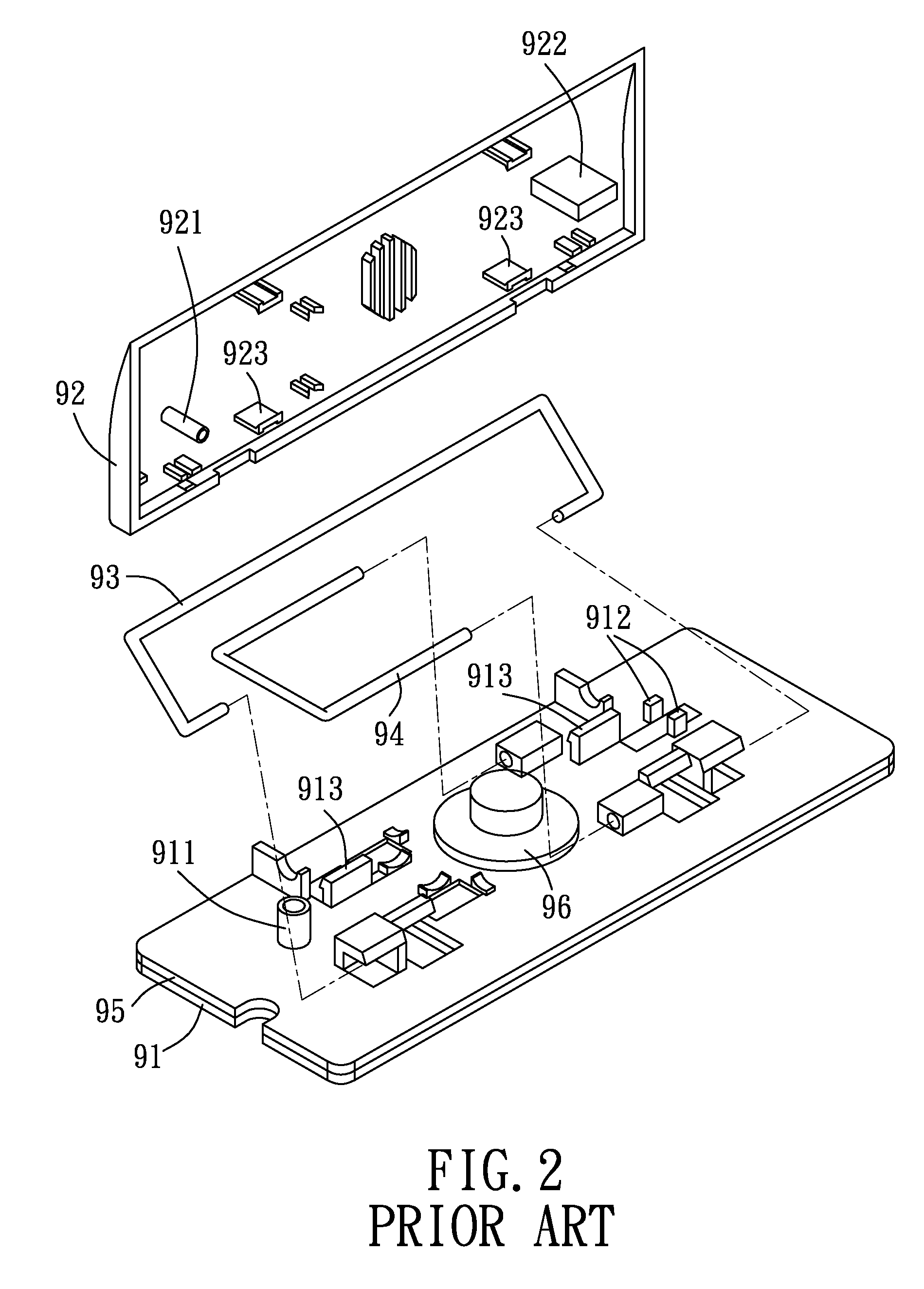
Nonetheless, the plastic components must be made with at least a predetermined thickness during the injection molding process in order to maintain a required strength, thereby undesirably increasing the manufacturing cost and the overall height of the keyswitch device 90.
A conventional way for increasing the strength of the plastic supporting seat 91 is to laminate an iron sheet on a bottom side of the supporting seat 91, which would further undesirably incur material and labor costs.
Metal supporting seat 91 and the keycap 92 by injection molding also have the drawback of relatively high manufacturing cost.

Method used


Image

  • Keyswitch device, supporting seat and key cap thereof
  • Keyswitch device, supporting seat and key cap thereof
  • Keyswitch device, supporting seat and key cap thereof

Examples


Embodiment Construction

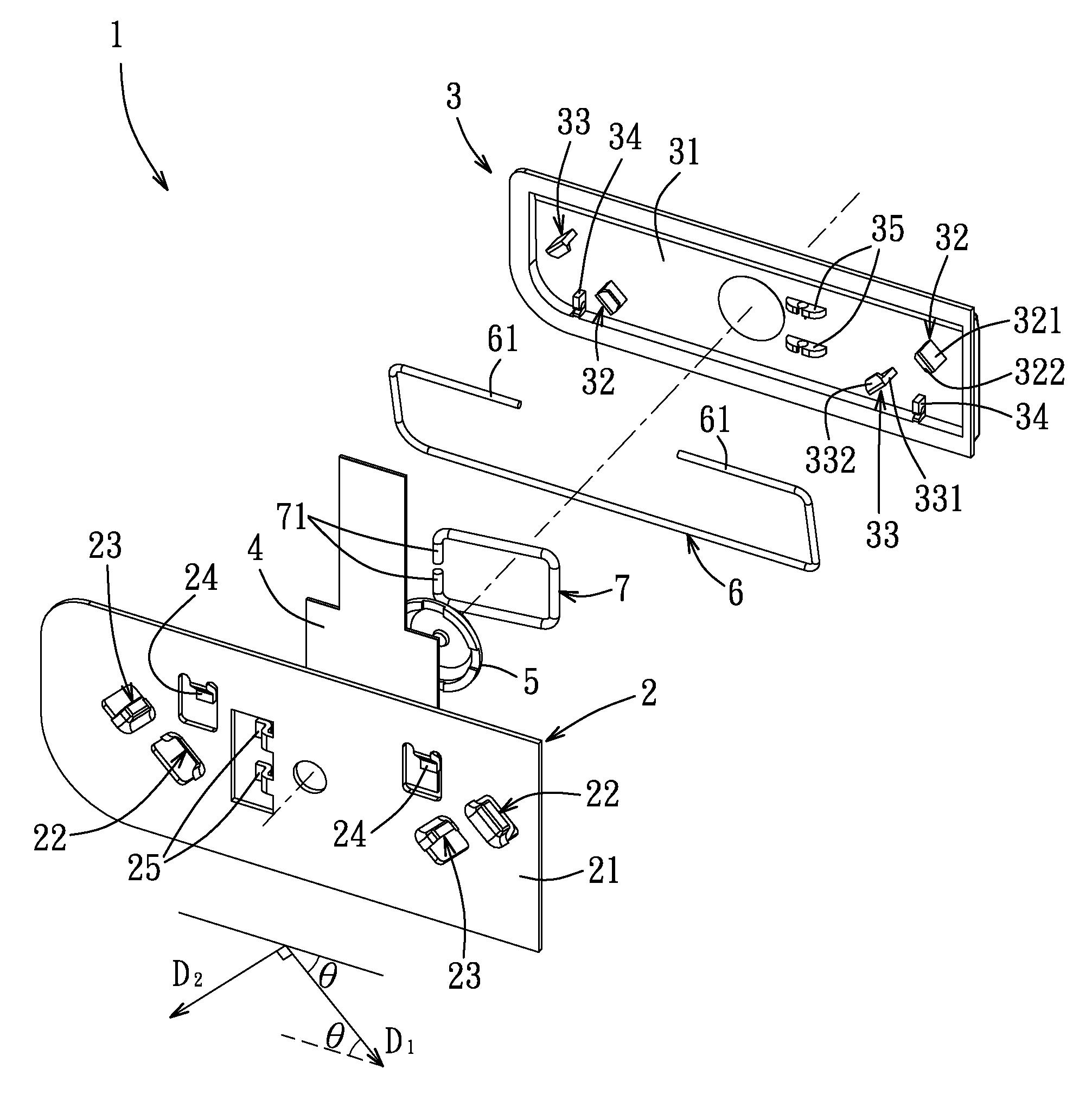
[0025]As shown in FIGS. 3 to 6, the embodiment of a keyswitch device 1 according to the present invention comprises a supporting seat 2, a key cap 3, a circuit board 4 disposed on the supporting seat 2, an elastic member 5 located between the key cap 3 and the circuit board 4, a rectangular first balancing member 6 and a rectangular second balancing member 7 that is shorter than the first balancing member 6.

[0026]In this embodiment, the supporting seat 2 is made of metal and is formed by a stamping process. The supporting seat 2 includes a base board 21, two spaced-apart first confining members 22 and two spaced-apart second confining members 23 that are formed on the base board 21, and two spaced-apart first pivoting members 24 and two spaced-apart third pivoting members 25. Each of the first pivoting members 24 and the third pivoting members 25 protrudes upwardly from the base board 21 and has a bent end section extending horizontally.

[0027]Each of the first confining members 22 h...


PUM


Abstract

A keyswitch device includes a supporting seat, a key cap, a circuit board disposed on the supporting seat, and an elastic member located between the key cap and the circuit board. The supporting seat includes a base board and two first confining members that are formed on the base board and that are spaced apart from each other. The key cap includes a cap body and two first hooks that engage respectively the first confining members, thereby inhibiting the key cap to move in horizontal directions with respect to the supporting seat, and allowing the key cap to move vertically in a range equal to the height of the first blocking parts of the first confining members. When the key cap is moved downward, the elastic member deforms to press the circuit board so as to generate a corresponding signal.

Description

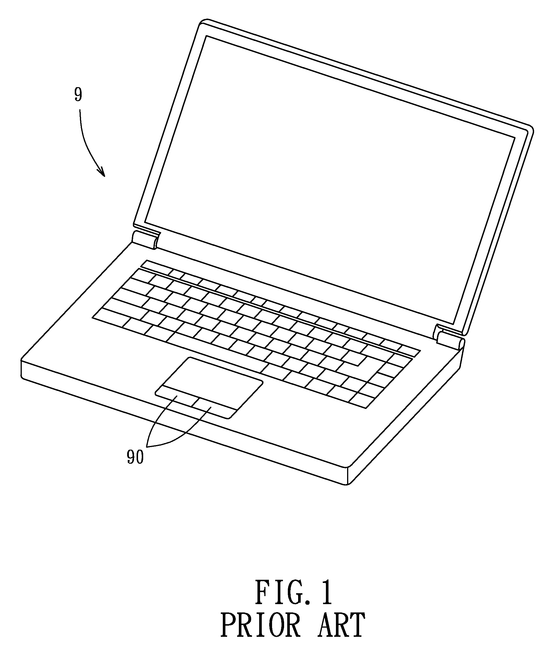
CROSS-REFERENCE TO RELATED APPLICATION[0001]This application claims priority of Taiwanese Application No. 100116498, filed on May 11, 2011, the entire disclosure of which is incorporated herein by reference.BACKGROUND OF THE INVENTION[0002]1. Field of the Invention[0003]The invention relates to a keyswitch device, more particularly to a keyswitch device that has a stable and relatively flat structure which comprises relatively few components.[0004]2. Description of the Related Art[0005]As shown in FIGS. 1 and 2, an electronic device 9, such as a personal digital assistant, a notebook computer or a keyboard, includes a conventional keyswitch device 90 serving as a command input device. The conventional keyswitch device 90 includes a supporting seat 91, a key cap 92 for pressing, a first balancing member 93 and a second balancing member 94 connected pivotally between the supporting seat 91 and the key cap 92, a circuit board 95, and a resilient dome 96 disposed on the circuit board 95...

Claims


Application Information

Patent Timeline
Patent Type & Authority Patents(United States)
IPC IPC(8): H01H3/12
CPCH01H3/125
Inventor LIANG, CHEN-YICHUANG, CHENG-HSIANGCHEN, CHUN-CHIENBAI, SHUN-DEKAO, SAN-PAO
Owner WISTRON CORP
Learn More