Method for securing a panel over a gap in an exterior portion of a building

a technology for exterior portions and panels, applied in the field of brackets, can solve the problems of requiring a relatively large amount of time to piece together and install, requiring a relatively large amount of time to install, and requiring a relatively large amount of tim

Inactive Publication Date: 2014-02-25
IANNELLI ANTHONY M
View PDF5 Cites 5 Cited by
  • Summary
  • Abstract
  • Description
  • Claims
  • Application Information

AI Technical Summary

Benefits of technology

[0004]The present bracket is adapted to be mounted on a frame member and to secure a panel over a gap in an exterior portion of a building. The subject bracket basically comprises an anchoring end adapted to be secured to the frame member; an elongated body defining a recess

Problems solved by technology

In the past, relatively labor intensive assemblies known as chicken ladders were installed in the gap extending between the eave or roof overhang and the upper course of brick or other material defining the outer wall of the building.
The

Method used


Image

  • Method for securing a panel over a gap in an exterior portion of a building
  • Method for securing a panel over a gap in an exterior portion of a building
  • Method for securing a panel over a gap in an exterior portion of a building

Examples


Embodiment Construction

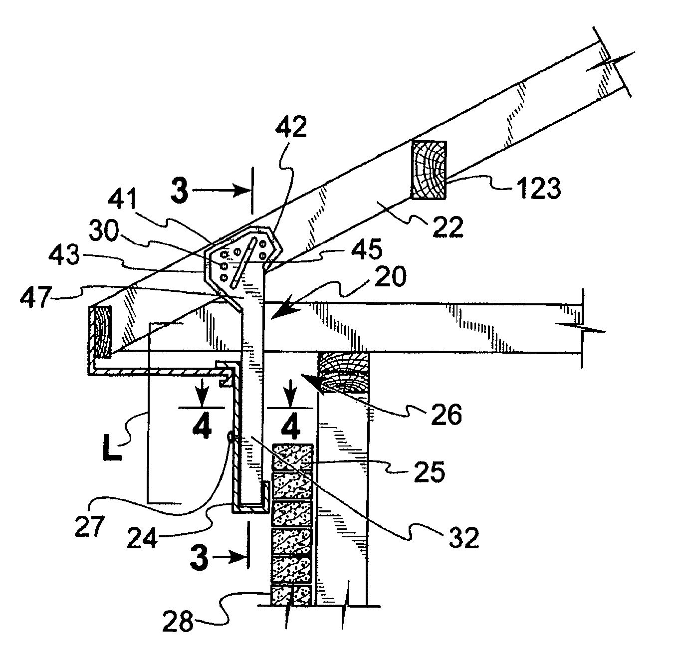
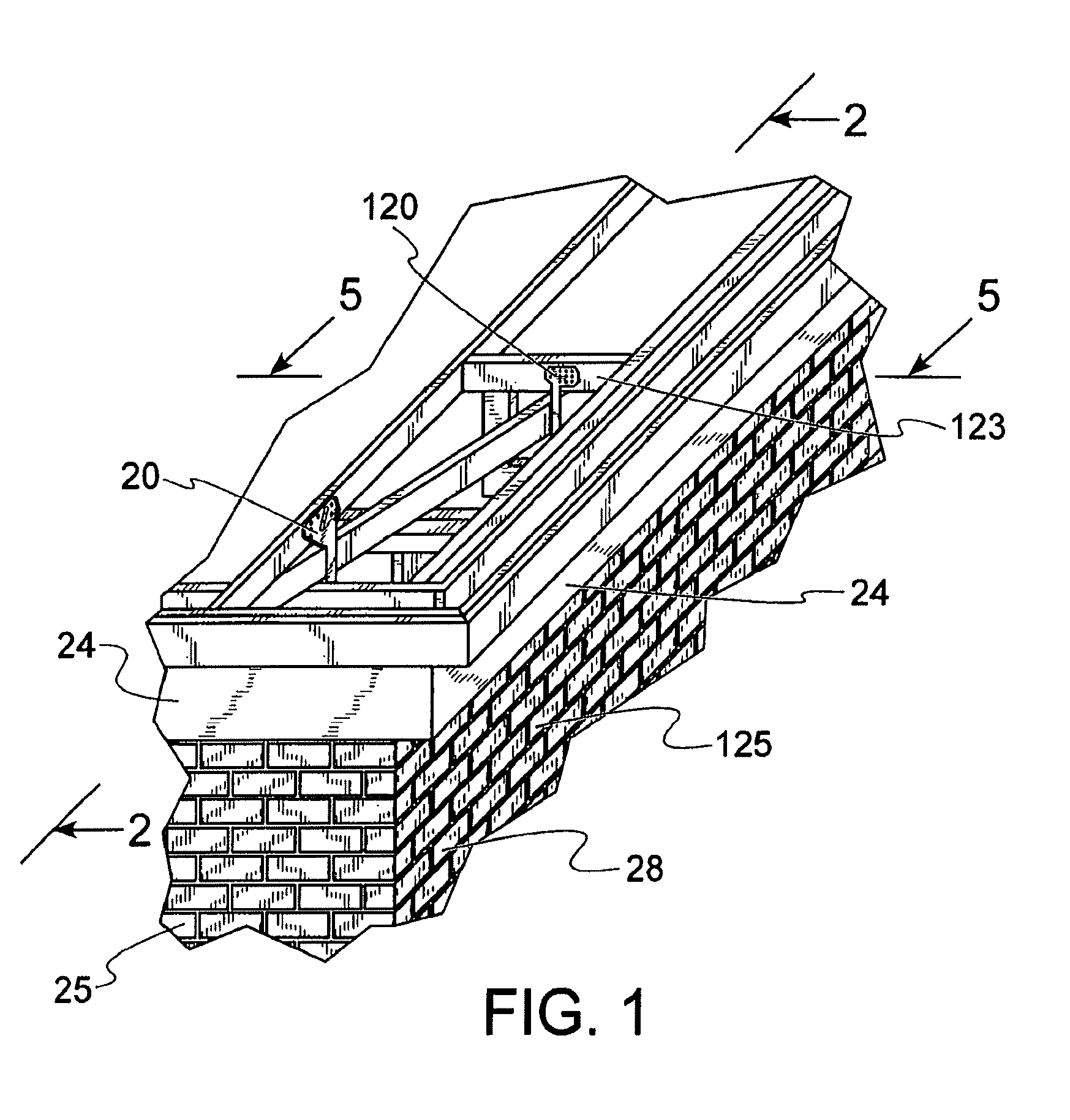
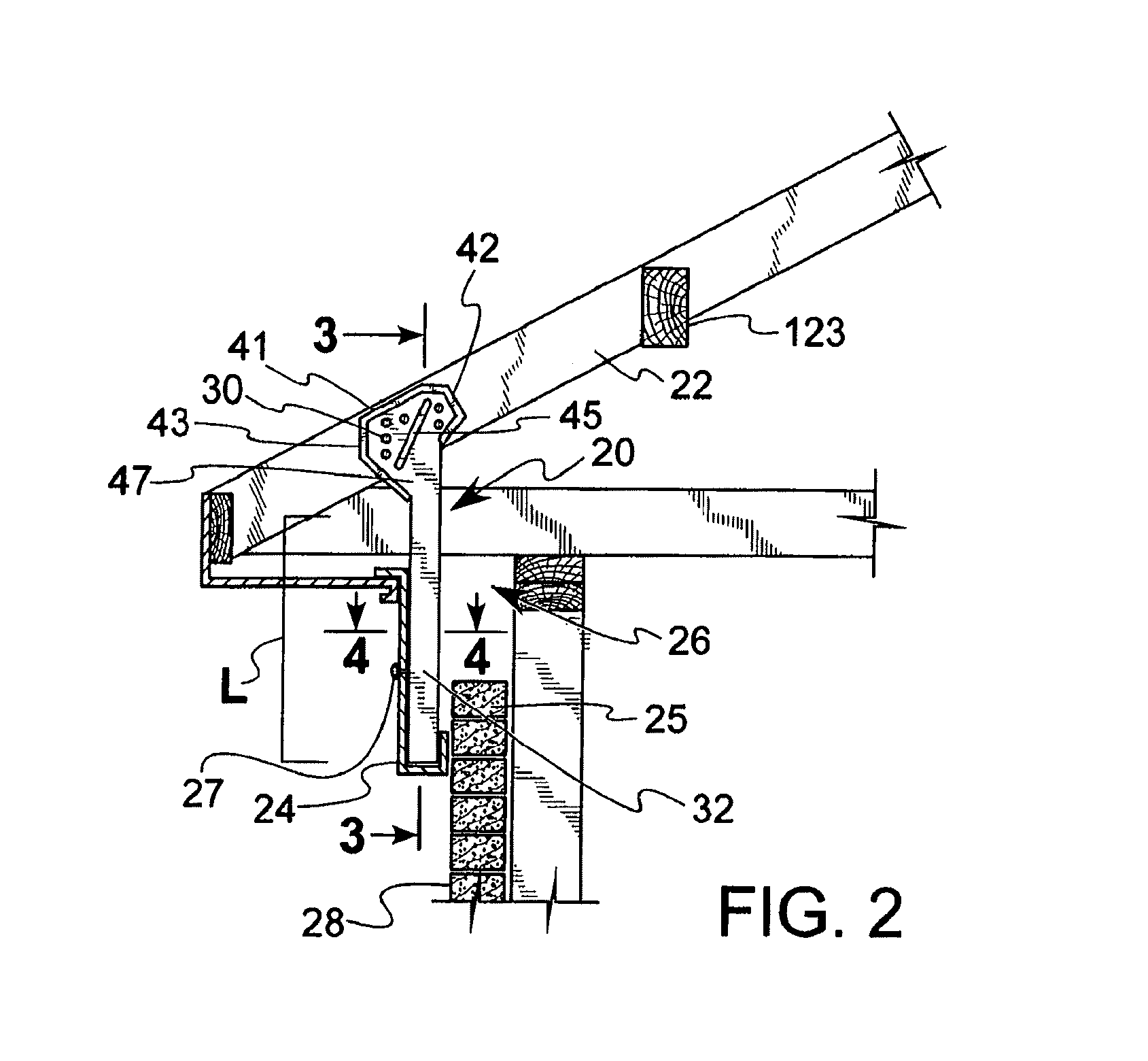
[0017]As illustrated in FIGS. 2-4, the present bracket, generally designated 20, is adapted to be mounted on a frame member 22 and to secure a panel 24 over a gap 26 in an exterior portion of a building 28 (FIG. 1). The bracket 20 basically comprises an anchoring end 30 adapted to be secured to the frame member 22, an elongated body 32 defining a recess 34 and having at least one panel-facing portion 36 and a length L substantially sufficient to span the gap 26 in the exterior portion of the building 28, and at least one opening 40 in the body 32 adjacent to said at least one panel-facing portion 36, said opening 40 extending into the recess 34.

[0018]As further illustrated in FIGS. 2 and 3, in the first embodiment 20 of the present bracket, the following additional features are preferred. The anchoring end 30 of the bracket is disposed in fixed relation to the body 32. The anchoring end 30 comprises a pair of relatively spaced apart plates 42, 44 which are disposed to engage opposin...


PUM


Abstract

A pair of relatively spaced apart frame-engaging plates are provided on the anchoring end of the bracket. An elongated body extends downwardly from the anchoring end and spans a gap between the roof frame member to which the anchoring end is attached and the exterior brick. An elongated opening extends between panel facing edge portions of the elongated body and into an insert receiving recess. A frieze panel adapted to cover the gap between the roof frame member and the brick is mounted on the bracket by nailing it to a wooden insert mounted in the recess.

Description

CROSS REFERENCE TO RELATED APPLICATIONS[0001]This application is a divisional application of U.S. patent application Ser. No. 09 / 635,281, filed Aug. 9, 2000, the disclosure of which is incorporated by reference herein in its entirety.BACKGROUND OF THE INVENTION[0002]This invention relates to brackets for use with wooden frame members of buildings and more particularly to brackets for connecting a frieze or other cover panel to such frame members.[0003]In the past, relatively labor intensive assemblies known as chicken ladders were installed in the gap extending between the eave or roof overhang and the upper course of brick or other material defining the outer wall of the building. The chicken ladder was typically fashioned onsite and involved some risk of injury because the 1×6 or 1×8 lumber employed in the assembly was heavy and unwieldy. It also required a relatively large amount of time to piece together and install. Thus, the present inventor was confronted with the problem of ...

Claims


Application Information

Patent Timeline
IPC IPC(8): E04D13/158
CPCE04D13/158
Inventor IANNELLI, ANTHONY, M.
Owner IANNELLI ANTHONY M
Why Eureka
Try Eureka