Modular overhead storage

a module and overhead storage technology, applied in the direction of machine supports, dismountable cabinets, furniture parts, etc., can solve the problems of consuming valuable floor and storage space, requiring higher inventory costs, and limited width to that of a single plank, platform or other member, so as to reduce noise and vibration, and facilitate the adjustment of lengths

Active Publication Date: 2014-02-25
PARALLAX GROUP INT
View PDF77 Cites 27 Cited by
  • Summary
  • Abstract
  • Description
  • Claims
  • Application Information

AI Technical Summary

Benefits of technology

[0010]Each of the platforms in the rack can advantageously be supported from above by one, two, or more pairs of legs. Legs can alternatively or additionally be disposed between the platforms. Preferred legs are telescoping, allowing easy adjustment of their lengths. It is further contemplated that the telescoping mechanism can have a finger operable detent that cooperates with a catch to fix the length until the user can insert a secure pin.
[0011]In another aspect, a polymeric ring can be advantageously positioned at an end of one of the telescoping components of a leg to reduce noise and vibration. Similarly, polymeric rings can be placed at the ends of the longitudinal supports.

Problems solved by technology

One problem with known storage racks, whether overhead or floor supported, is that the width is limited to that of a single plank, platform, or other member.
This causes wholesalers and retailers to stock several different widths to accommodate different user demands, which in turn consumes valuable floor and storage space, and requires higher inventory costs.

Method used


Image

  • Modular overhead storage
  • Modular overhead storage
  • Modular overhead storage

Examples


Embodiment Construction

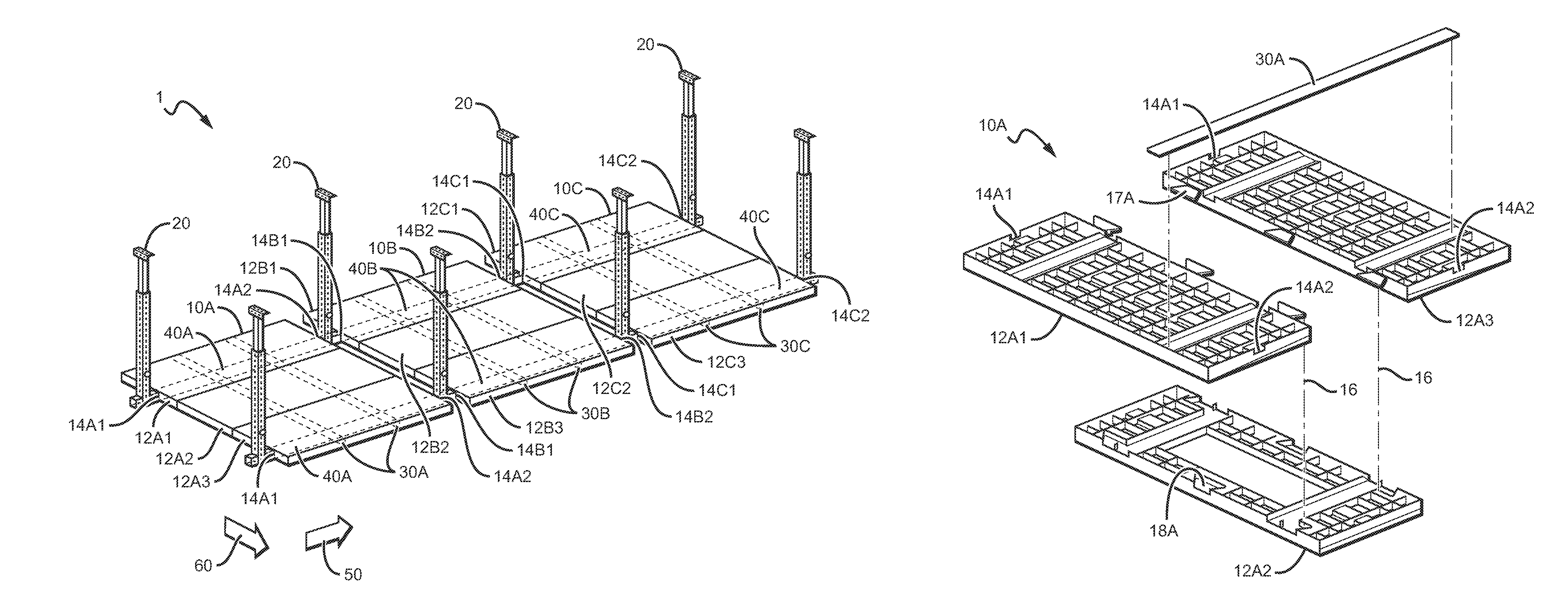
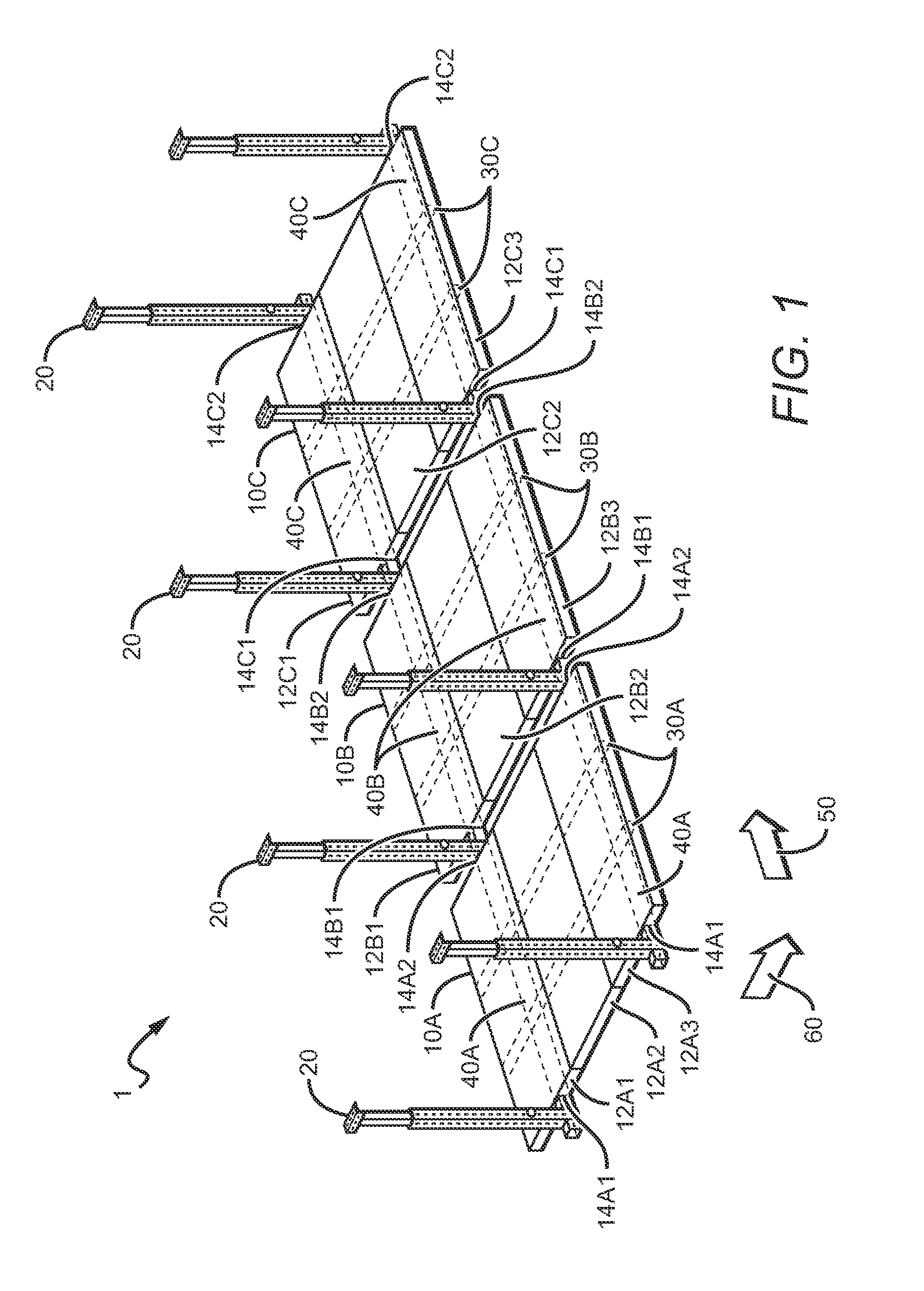
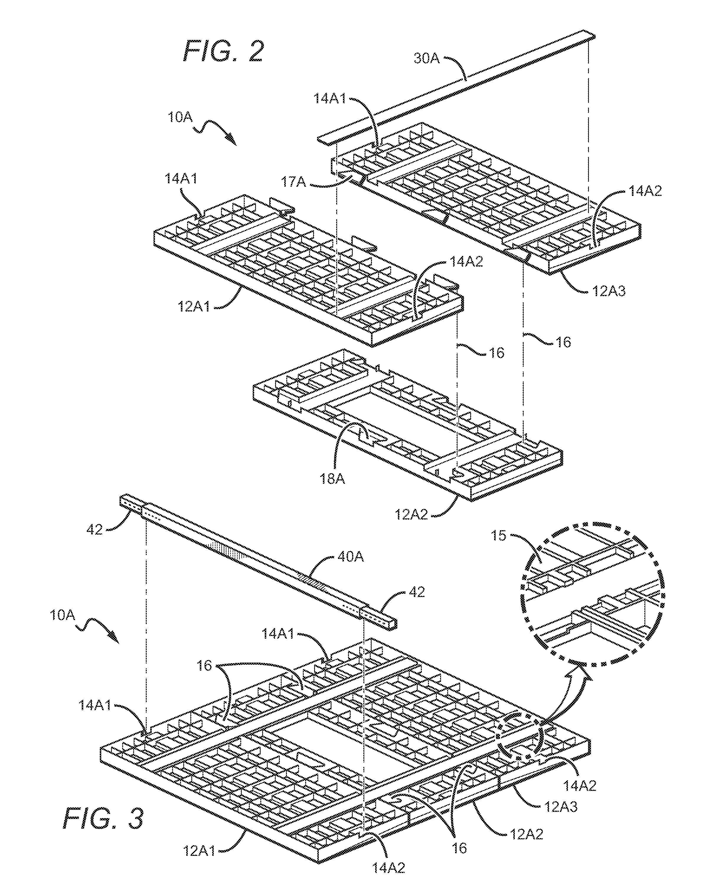
[0024]In FIG. 1, a storage rack 1 generally includes platforms 10A, 10B, and 10C, and legs 20. Each of the platforms 10A, 10B, and 10C comprises three segments 12A1-12A3 for platform 10A, 12B1-12B3 for platform 10B, 12C1-12C3 for platform 10C. There is a pair of transverse supports 30A-30C underneath each of the platforms, and two longitudinally oriented supports 40A-40C beneath each of the pairs of transverse supports 30A-30C, respectively. The platforms 10A, 10B, and 10C are coupled together at the ends of the longitudinally oriented supports 40A-40C via a series of recesses 14A1-14A2 for segments 12A1 and 12A3, recesses 14B1-14B2 for segments 12B1 and 12B3, 14C1-14C2 for segments 12C1 and 12C3, respectively, and held from above using legs 20.

[0025]It should be apparent from FIG. 1 that the various platforms are connected to one another in a first direction 50, whereas each of the platforms has segments that connect to one another along a second direction 60, which is not only dif...


PUM


Abstract

A storage system comprises a rack of multiple platforms connectable to one another in a first direction, where each of the platforms has segments that connect to one another along a direction other than the first direction, via a user-operable coupling. The platforms are preferably rectangular, and are connected at their long ends. The segments of each platform are also preferably rectangular, but they are connected along their long sides. In such embodiments, the connection between platforms is perpendicular to the length of the rack, while the connection between segments is parallel to the length of the rack. The segments of individual platforms are preferably coupled together with snap fit connections, and supported from their undersides by transverse supports, and the transverse supports are supported from their undersides by longitudinal supports via recesses on the segments. The transverse supports are preferably perpendicular to the longitudinal supports.

Description

[0001]This application is a continuation-in-part of U.S. patent application Ser. No. 11 / 479,480 filed Jun. 30, 2006, which claims the benefit of U.S. Provisional Application No. 60 / 697,468 filed Jul. 7, 2005 and U.S. Provisional Application No. 60 / 726,746 filed Oct. 14, 2005. These and all other extrinsic materials discussed herein are incorporated by reference in their entirety. Where a definition or use of a term in an incorporated reference is inconsistent or contrary to the definition of that term provided herein, the definition of that term provided herein applies and the definition of that term in the reference does not apply.FIELD OF THE INVENTION[0002]The field of the invention is overhead suspension storage racks.BACKGROUND[0003]Many different types of overhead storage racks are known. Overhead storage racks are typically hung from the ceiling to provide storage space where space is at a premium, such as a garage.[0004]One problem with known storage racks, whether overhead ...

Claims


Application Information

Patent Timeline
Patent Type & Authority Patents(United States)
IPC IPC(8): A47F5/08A47B45/00
CPCA47F5/08A47B57/20A47B45/00A47B47/00A47B57/44A47B96/025A47F5/0892D06F57/125E04B9/18F16M13/027A47B43/003A47B96/021
Inventor THRUSH, BRUCEGRIMM, JOHN
Owner PARALLAX GROUP INT
Why Eureka
Try Eureka