Krueger

a leading edge flap and krueger technology, applied in the field of krueger, or leading edge flap, can solve the problems of reducing the circulation around the high-lift device, affecting the angle of the deployed krueger, and limiting the positioning of the deployed device, so as to reduce or eliminate the effect of divergen

Active Publication Date: 2014-02-25
AIRBUS OPERATIONS LTD
View PDF29 Cites 3 Cited by
  • Summary
  • Abstract
  • Description
  • Claims
  • Application Information

AI Technical Summary

Benefits of technology

[0010]The invention is advantageous in that the flow deflector acts to reduce, or eliminate, slot divergence, particularly where this cannot otherwise be achieved due to kinematic constraints. The profile of the upper aerodynamic surface of the Krueger is dictated by the profile of the lower surface of the main wing element, since these must match when the Krueger is retracted. By directing the airflow away from adjacent the trailing edge of the lower aerodynamic surface of the Krueger towards the wing upper surface the flow deflector can reduce, or eliminate the slot divergence.
[0016]In a further alternative example, the flow deflector may be formed as a tab projecting downwardly from the Krueger lower aerodynamic surface at or adjacent the Krueger trailing edge. The tab creates a region or recirculating air just in front of the tab which has the effect of smoothly deflecting the bulk airflow over the lower aerodynamic surface of the Krueger downwardly towards the upper surface of the main wing element.
[0017]The flow deflector at or adjacent the Krueger trailing edge is not limited to a consistent thickness or angle across the span of the Krueger. The thickness may vary progressively across the span or may alternatively be applied in a stepped variation to form a castellated or sawtooth pattern. A stepped variation can act as vortex generators by introducing multiple vortical flows into the slot across the Krueger span. This can improve mixing between the wake from the Krueger trailing edge and the flow through the slot which can reduce the adverse interference between the wake and the wing boundary layer. There is therefore a resultant improvement in the maximum lift of the wing.
[0018]It is known that a thick Krueger trailing edge produces a wake which could disturb the wing boundary layer. The flow deflector has the effect of increasing the Krueger wake thickness. Accordingly, there is a trade off between the positive effect of increasing the circulation around the Krueger to suppress the suction wing peak as a result of improved slot convergence, and disturbance to the wing boundary layer by the interaction of the thickened Krueger wake due to the increased wake thickness caused by the flow deflector. The Krueger / flow deflector design therefore needs to be optimised for maximum aerodynamic performance.
[0019]Integrally forming the flow deflector with the Krueger may provide advantages in terms of reduced maintenance, reduced parts count, reduced production time, improved stiffness and weight saving. However, a detachable flow deflector may provide advantages for ease of removal for repair, testing etc.
[0021]The slot, which opens up between the Krueger and the main wing element when the Krueger is deployed, is preferably convergent forward of the flow deflector in the direction of the onset flow. The flow deflector reduces, or eliminates, divergence of the slot adjacent the Krueger trailing edge.

Problems solved by technology

If the slot is convergent-divergent the circulation around the high-lift device is reduced due to the less than optimal aerodynamic setting.
However, kinematic constraints, particularly for Krueger actuation mechanisms, can limit the positioning of the deployed device and create a convergent-divergent slot.
In particular, the available extent of rotation of the Krueger during deployment will affect the angle of the deployed Krueger.
Further rotation to an aerodynamically more desirable angle may not be possible without resulting in a more complex, heavier design.

Method used


Image

  • Krueger
  • Krueger
  • Krueger

Examples


Embodiment Construction

)

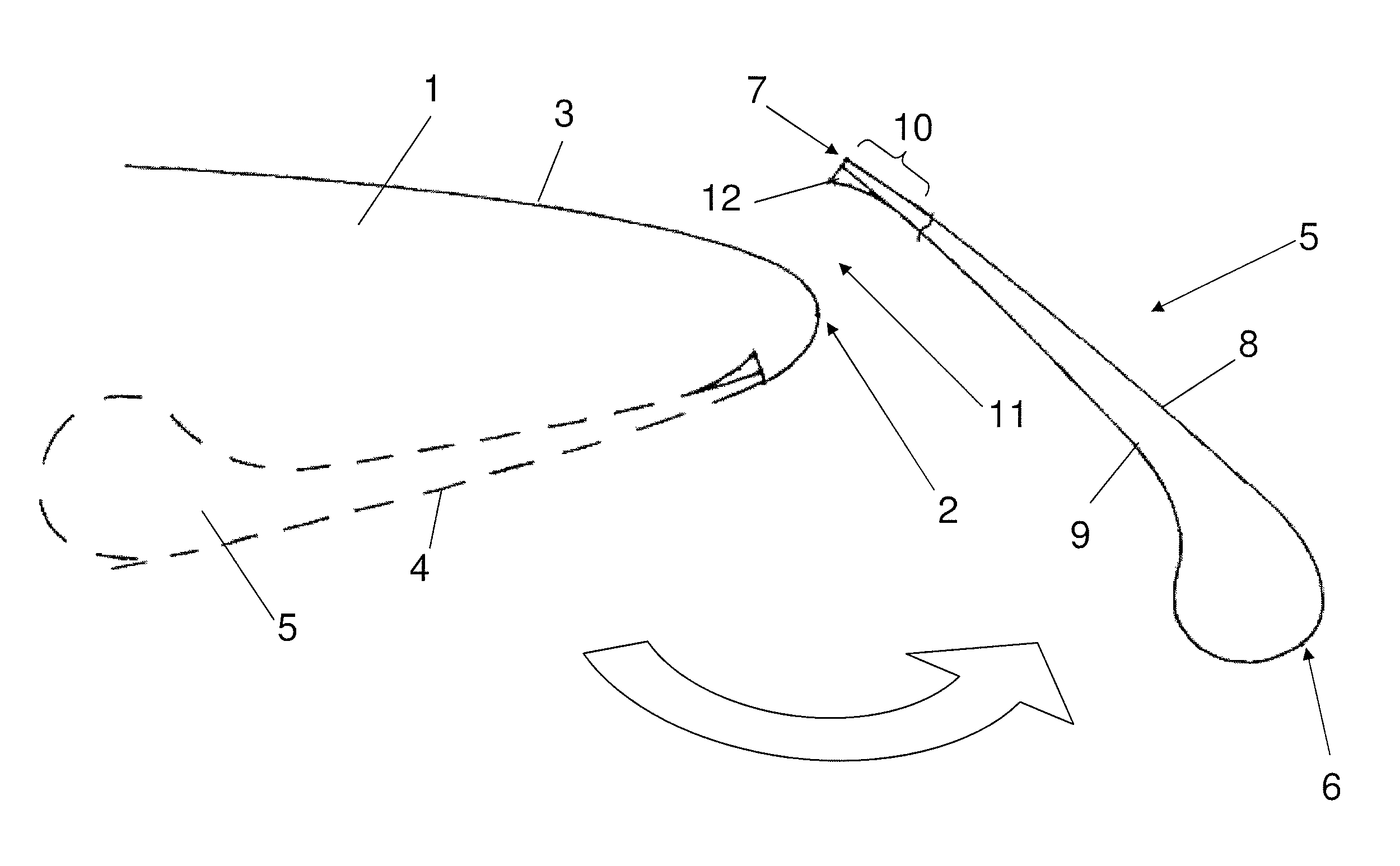
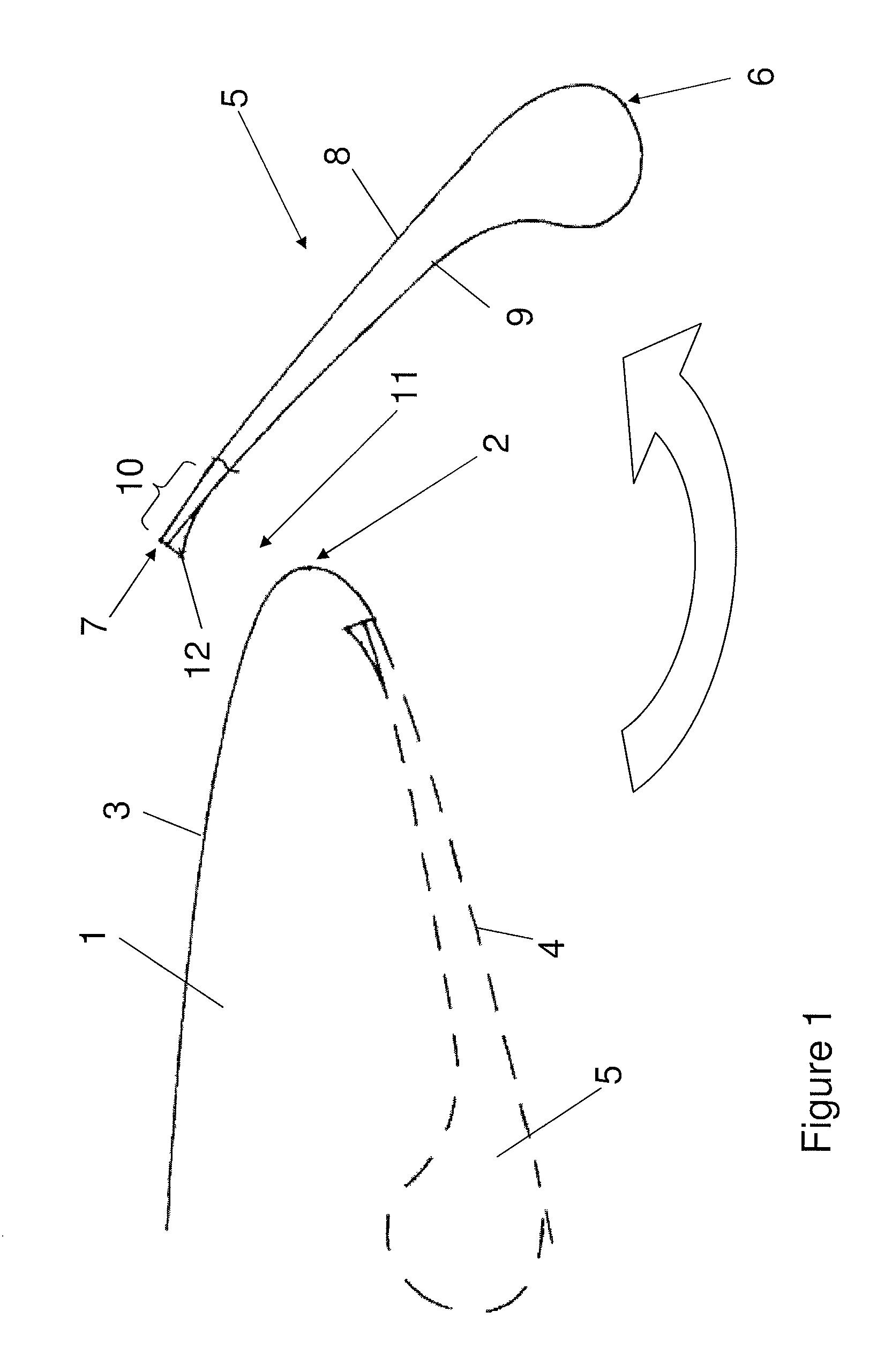
[0027]FIG. 1 illustrates an aircraft wing comprising a main (“fixed”) wing element 1 having a leading edge 2, an upper aerodynamic surface 3, and a lower aerodynamic surface 4. The upper and lower aerodynamic surfaces 3, 4 meet at the leading edge 2. A Krueger 5 is mounted to the main wing element 1 for movement between a retracted position (shown in broken line) and a deployed position (shown in full line). The leading edge Krueger 5 is a high-lift device deployed at low speed and high incidence to increase the camber and maximum lift coefficient of the wing. The Krueger is movable between its deployed and retracted positions by a Krueger actuation mechanism, which has been omitted from FIG. 1 for clarity.

[0028]The deployed Krueger 5 has a leading edge 6, a trailing edge 7, an upper aerodynamic surface 8 and a lower aerodynamic surface 9. The upper and lower aerodynamic surfaces 8, 9 meet at the leading and trailing edges 6, 7. A region of the Krueger adjacent the trailing edge 7 ...


PUM


Abstract

A Krueger, or leading edge flap, deployable from a lower aerodynamic surface of an aircraft main wing element so as to form a slot between the Krueger and the main wing element when deployed, the deployed Krueger having a leading edge, a trailing edge and upper and lower aerodynamic surfaces extending between the leading edge and the trailing edge, and a flow deflector which provides an effectively divergent flap profile thickness in the downstream direction at or adjacent the Krueger trailing edge so as to direct airflow away from the lower aerodynamic surface of the deployed Krueger towards an upper aerodynamic surface of the main wing element. Also, aircraft wing assembly including a main wing element and the Krueger.

Description

RELATED APPLICATIONS[0001]The present application is based on, and claims priority from, British Application Number 1018176.6, filed Oct. 28, 2010, the disclosure of which is hereby incorporated by reference herein in its entirety.FIELD OF THE INVENTION[0002]The present invention relates to a Krueger, or leading edge flap, for an aircraft wing.BACKGROUND OF THE INVENTION[0003]A Krueger, or leading edge flap, is a high-lift device deployable from the lower aerodynamic surface of an aerofoil, such as an aircraft wing. When stowed the Krueger trailing edge is disposed at or near the wing leading edge, and a portion of the Krueger device makes up part of the wing lower surface. When deployed the Krueger rotates forwardly from a hinge near the wing leading edge, and the Krueger trailing edge remains adjacent the wing leading edge.[0004]Whilst the Krueger is functionally similar to a slat when deployed, slats are deployed forwardly from the wing leading edge.[0005]Leading edge high-lift d...

Claims


Application Information

Patent Timeline
Patent Type & Authority Patents(United States)
IPC IPC(8): B64C3/50
CPCB64C9/24Y02T50/44B64C2009/143Y02T50/40
Inventor BROWN, JAMESKAY, EDMUND
Owner AIRBUS OPERATIONS LTD
Why Eureka
Try Eureka