Vibrating structural gyroscope with quadrature control

a gyroscope and vibration structure technology, applied in the field of vibration structure gyroscopes, can solve the problems of machining errors and mask misalignment, non-uniform size of sense elements, and inability to meet the requirements of the measurement instrument, so as to improve the tuning of the gyroscope. the effect of reducing the destructive interference between the plurality of drive axes, reducing the quadrature signal, and improving the tuning of the gyroscop

Inactive Publication Date: 2014-03-04
WATSON INDUSRIES
View PDF56 Cites 28 Cited by
  • Summary
  • Abstract
  • Description
  • Claims
  • Application Information

AI Technical Summary

Benefits of technology

[0015]Various embodiments of the invention include an apparatus and / or method that corrects for tuning errors in vibrating structure gyroscopes that are configured to be driven along a plurality of axes by correcting for the quadrature signal directly along the input of the drive axes and without use or need for dedicated torque elements. The correction is accomplished by introducing a phase offset in the drive signal of one or more of the drive elements relative to other drive elements to minimize or reduce the quadrature signal. The tuning may be accomplished as a one time “set and forget” adjustment, as a manual adjustment performed at the discretion of the user, or as a closed loop active correction system. The technique improves the tuning of the resonator assembly, rather than merely compensating for inherent tuning errors. Accordingly, for various embodiments of the invention, the destructive interference between the plurality of drive axes is reduced. Conservation of vibrational energy present in the resonator is thus enhanced, with less vibrational energy transferred to the support structure.
[0019]Embodiments of the present invention take advantage of the variation between the resonant frequencies of a resonator assembly generated along two (or more) drive axes. The phase difference between the vibration characteristics can be used to correct the input drive signals of the drive elements along the respective axes so that phase difference and the attendant quadrature signal is reduced, minimized or substantively eliminated.
[0022]In some embodiments, the method further includes providing at least one drive sensor adapted to sense a driving oscillation of the resonator assembly, providing a phase-locked loop driving system having an input operatively coupled with the at least one driving sensor and having outputs operatively coupled to the first and the second of the plurality of drive elements and causing the phase-locked loop driving system to output the first and the second drive signals, the first and the second drive signals having a frequency that substantially matches the frequency of the drive oscillation.

Problems solved by technology

Each of these components can introduce non-uniformities to the resonator assembly.
Also, the drive and / or sense elements may also be of varying thickness or density and / or of non-uniform size.
Machining errors and mask misalignment can also contribute to non-uniformity.
Furthermore, the various appurtenances that interface with the resonator assembly (e.g., wires, contact tabs) and that hold the assembly together (e.g., solder, adhesives for the elements) can also be of differing mass between the elements, thereby introducing further non-uniformities to the resonator assembly.
Moreover, thermal gradients (transient or steady state) that are present on the resonator assembly can introduce further non-uniformities.
The non-uniformities of the resonator assembly can cause a quadrature signal to appear at the sense element.

Method used


Image

  • Vibrating structural gyroscope with quadrature control
  • Vibrating structural gyroscope with quadrature control
  • Vibrating structural gyroscope with quadrature control

Examples


Embodiment Construction

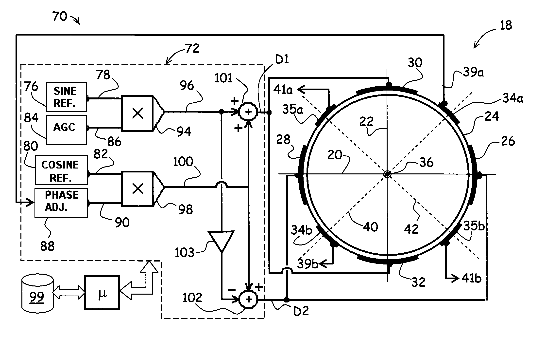
[0040]Referring to FIG. 1, an example of a resonator assembly 18 that can be driven along two independent drive axes 20 and 22 is depicted to establish nomenclature. The resonator assembly 18 includes a resonator element 24 (depicted as a cup resonator), a first pair of drive elements 26, 28, a second pair of drive elements 30, 32, and various sense element pairs 34a, 34b and 35a, 35b. Both drive element pairs 26, 28 and 30, 32 are operatively coupled with the resonator element 24, the resonator element 24 defining a central axis 36 about which rotation of the resonator assembly 18 is sensed.

[0041]The drive elements 26, 28 and 30, 32 of each drive element pair are positioned in diametric opposition to each other about the central axis 36. In this embodiment, the first and second drive element pairs 26, 28 and 30, 32 define the first drive axis 20 and the second drive axis 22, respectively. Herein, a “drive axis” defines a vector along which a forcing function is imposed to sustain a...


PUM


Abstract

An apparatus and / or method that corrects for tuning errors in vibrating structure gyroscopes that are configured to be driven along a plurality of axes without the need for dedicated torque elements. The correction is accomplished by introducing a phase offset in the drive signal of one or more of the drive elements relative to other drive elements to minimize or reduce the quadrature signal. The tuning may be accomplished as a one time “set and forget” adjustment, as a manual adjustment performed at the discretion of the user, or as a closed loop active correction system. The technique improves the tuning of the resonator assembly, rather than merely compensating for the mistuning. Accordingly, for various embodiments of the invention, the destructive interference between the plurality of drive axes is reduced. Conservation of vibrational energy present in the resonator is thus enhanced, with less vibrational energy transferred to the support structure.

Description

RELATED APPLICATION[0001]The present application claims the benefit of U.S. Provisional Patent Application No. 61 / 105,236, filed on Oct. 14, 2008, the disclosure of which is hereby incorporated by reference in its entirety.FIELD OF THE INVENTION[0002]The present disclosure is directed generally to the field of gyroscopes. More specifically, the present disclosure is directed to a vibrating structural gyroscope having quadrature control.BACKGROUND OF THE INVENTION[0003]Vibrating structural gyroscopes (VSGs) have found use in a number of applications involving the detection of rotational rate and position, including attitude sensors and gyrocompasses. Rotational rate and / or position is typically determined by exciting a resonator along one or more drive axes to drive the resonator into an oscillation or vibration pattern and detecting a change in the output signal. The output signal may include a “quadrature” signal or component, herein defined as the component of a complex signal tha...

Claims


Application Information

Patent Timeline
Patent Type & Authority Patents(United States)
IPC IPC(8): G01C19/00
CPCG01C19/5691
Inventor WATSON, WILLIAM, S.
Owner WATSON INDUSRIES
Why Eureka
Try Eureka