Cladding element for device sections of incinerators

a technology for incinerators and cladding elements, which is applied in the direction of grates, hollow bar grates, combustion processes, etc., to achieve the effects of easy bending, easy fabrication of cladding elements, and greater wall thickness

Inactive Publication Date: 2014-03-04
I C E IND CONTRACTORS & ENGINEERS AG
View PDF19 Cites 2 Cited by
  • Summary
  • Abstract
  • Description
  • Claims
  • Application Information

AI Technical Summary

Benefits of technology

[0017]One of the main advantages to such a mode of construction is that, as opposed to conventional solutions, components requiring heavy, complex and expensive compositions need no longer be fabricated, instead of which only individual sheets (lower and upper plate) have to be machined, which then are especially easy and logical to assemble. The sheet machining processes required for this purpose only encompass standard methods, such as cutting, drilling and in particular milling, i.e., all procedures that are suitable for largely automated fabrication on machining benches, and thus permit an efficient and cost-effective production. In addition, the basic material for both the lower plate and upper plate can in principle be a conventional steel, which of course is also beneficial in terms of cost.
[0026]As a whole, the proposed solution makes it possible to make the current structural designs of water-cooled elements less expensive to manufacture, and above all more easy to service. Expensive repairs of corresponding leaks are no longer required, and entire fill shafts must also no longer be replaced at a high outlay, for example. These intricate repair jobs can be avoided with the proposed weld-plated, medium-cooled cladding elements. The integration of cladding elements only still requires a suitable substructure, i.e., in the case of shaft walls, a rib frame, for example, to which cladding elements are tightly bolted. If the applied hard plating of a cladding element becomes damaged by the continuous sliding motion of the garbage, individually damaged cladding elements can be replaced very easily. The substructure, i.e., the rib frame, can be used time and again to accommodate the cladding elements. This makes the entire structural design and incurred service work much less expensive.

Problems solved by technology

However, this publication involves cast parts, in particular cast parts with a high chromium content, which also are not provided with specific features for the targeted distribution of cooling air or cooling medium streams.

Method used


Image

  • Cladding element for device sections of incinerators
  • Cladding element for device sections of incinerators
  • Cladding element for device sections of incinerators

Examples


Embodiment Construction

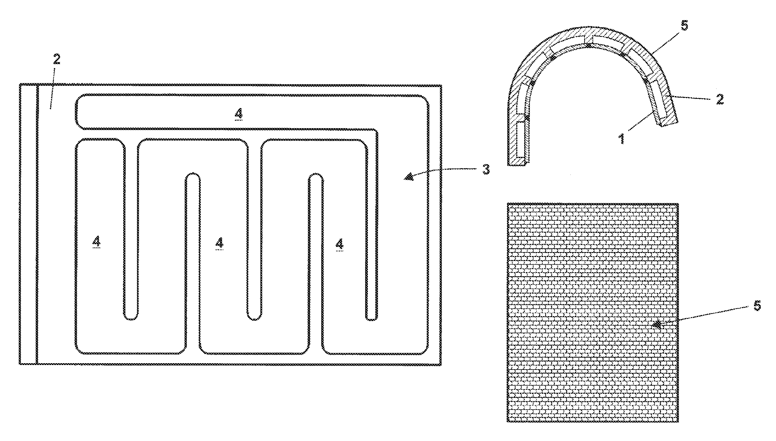
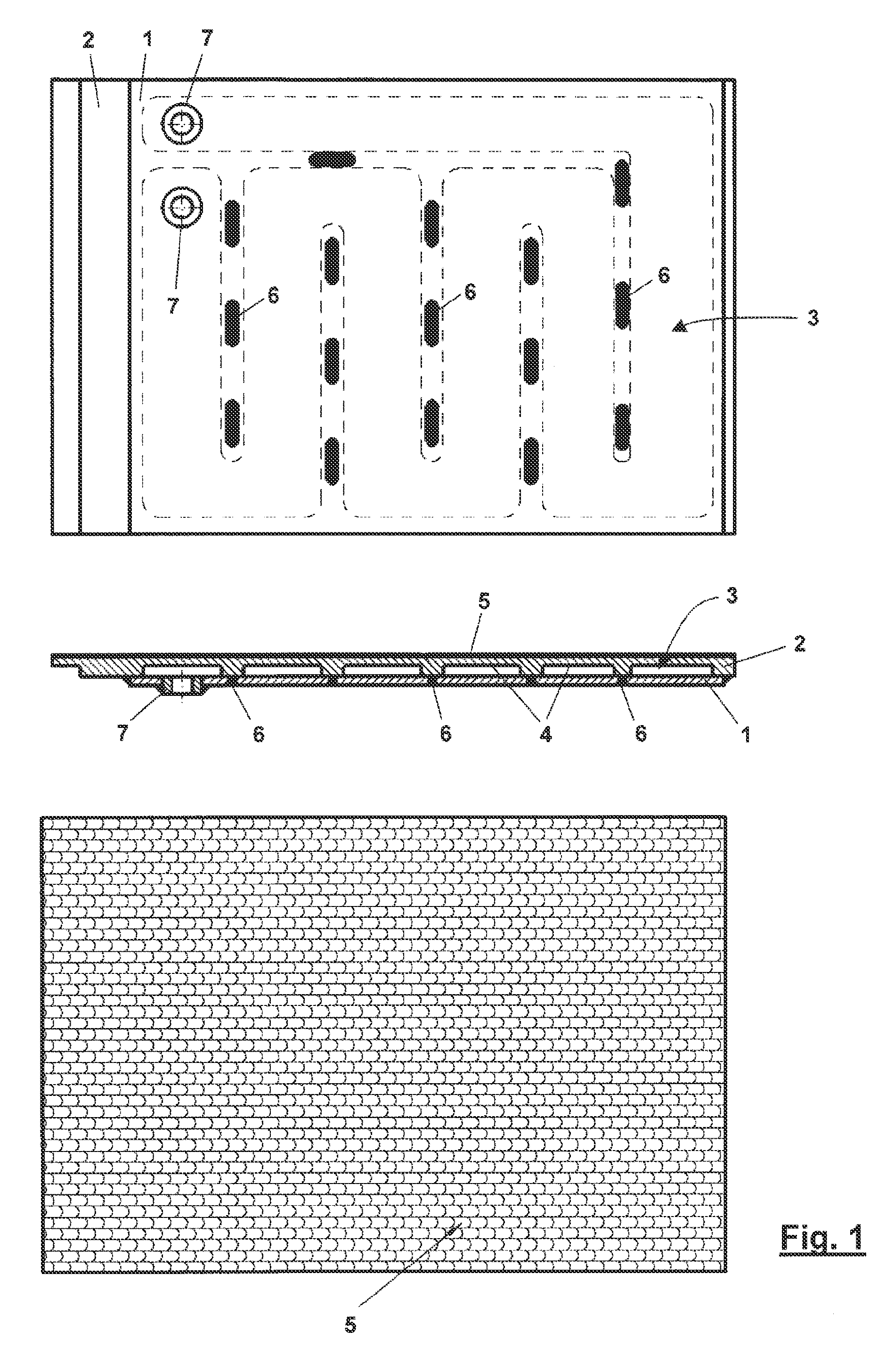
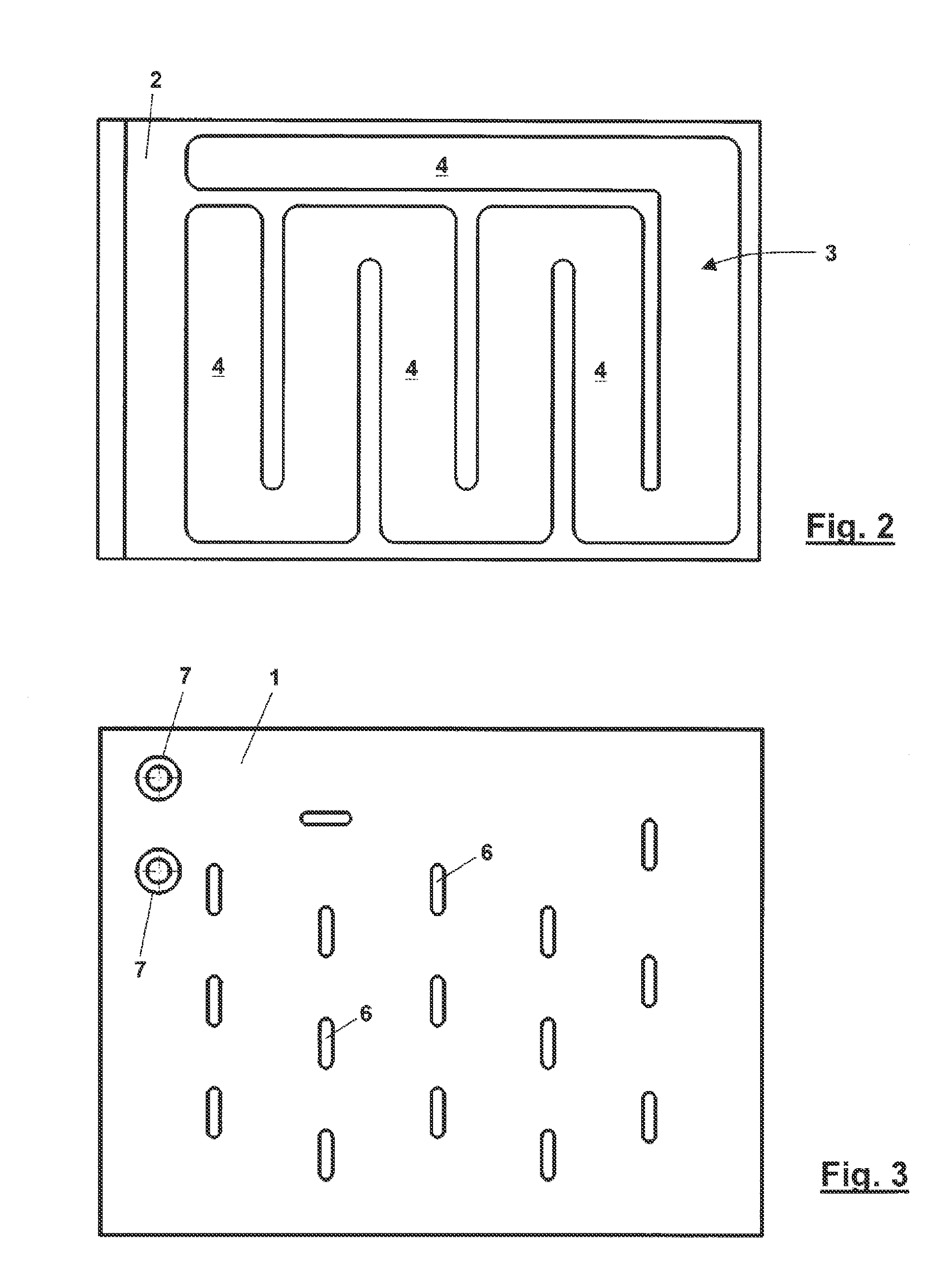
[0038]FIG. 1 shows a flat cladding element according to the invention for device sections of incinerators viewed from below, in cross section and from above. The cladding element has an upper plate 2 made of steel, and a lower plate 1 made of steel, which lie one atop the other, and have a channel 3 arranged between them for guiding a cooling medium through the cladding element. In the depicted exemplary embodiment, the channel 3 is incorporated into the upper plate 2 as a meandering milled slot 4. The side of the upper plate 2 facing away from the lower plate 1 has a weld plating 5. As mentioned at the outset, the weld plating 5 is a hard applied layer with an especially high abrasion resistance that is applied via robotic welding, for example. Of course, the goal is to achieve other characteristics, such as temperature resistance, high corrosion resistance, etc. This application layer normally has an overall layer thickness of several mm. A multiply structure for the application l...


PUM


Abstract

A cladding element for device sections of incinerators consists of a lower plate (1) made of steel and an upper plate (2) made of steel, which lie one atop the other and are tightly bonded with each other at least in the edge areas. A meandering channel (3) is formed between the lower plate (1) and upper plate (2) for guiding a cooling medium through the cladding element. Either the upper plate (2) or lower plate (1) is here a milled sheet with a meandering milled slot (4), which forms the channel (3), and the side of the upper plate (2) facing away from the lower plate (1) has a weld plating (5).

Description

CROSS REFERENCE TO RELATED APPLICATIONS[0001]This application claims priority under 35 U.S.C. §119 to Swiss Patent Application No. CH-00575 / 10 filed Apr. 21, 2010, the entire contents of which are incorporated herein by reference.FIELD OF THE INVENTION[0002]The invention relates to a cladding element for device sections of incinerators.BACKGROUND OF THE INVENTION[0003]The invention relates in particular to a cladding element for device sections of incinerators that consists of a lower plate made of steel and an upper plate made of steel, which lie one atop the other and are tightly bonded with each other at least in the edge areas, wherein a meandering channel is formed between the lower plate and upper plate for guiding a cooling medium through the cladding element.[0004]Device sections of incinerators, in particular garbage incinerators, are most often exposed to very high loads. These are thermal, chemical and mechanical loads, and frequently combinations thereof, of course. Sinc...

Claims


Application Information

Patent Timeline
Patent Type & Authority Patents(United States)
IPC IPC(8): F23M5/00F23M3/12
CPCF23H3/02F23R3/002
Inventor BACHMANN, MARCO
Owner I C E IND CONTRACTORS & ENGINEERS AG
Why Eureka
Try Eureka