Cable assembly having an improved circuit board

a technology of circuit board and cable assembly, which is applied in the direction of electrical apparatus construction details, coupling device connections, and association of printed circuit non-printed electric components, etc., can solve the problem of hard soldering of conductors to the flat top surface, and achieve the effect of improving the internal circuit and being convenient to be soldered

Active Publication Date: 2014-03-04
HON HAI PRECISION IND CO LTD
View PDF16 Cites 20 Cited by
  • Summary
  • Abstract
  • Description
  • Claims
  • Application Information

AI Technical Summary

Benefits of technology

[0006]Accordingly, an object of the present invention is to provide a cable assembly having an improved internal circuit board. The cable assembly includes a cover defining a cavity, a circuit board assembled in the cavity having a first surface and a second surface lower than the first surface. The cable assembly further has a cable including a jacket and a number of wires shrouded by the jacket. Each wire includes a inner coat and a conductor having a free end exposed outwardly from the inner coat. The free end of the conductor is soldered to the first surface, and the inner coat is disposed on the second surface. The height between the first surface and the second surface is substantially equal to a thickness of the inner coat. Thus, the free end of the conductor could extend straightly from the inner coat, and is convenient to be soldered on the top surface.

Problems solved by technology

It is hard to solder the conductors to the flat top surface due to a thickness of the coat.

Method used


Image

  • Cable assembly having an improved circuit board
  • Cable assembly having an improved circuit board
  • Cable assembly having an improved circuit board

Examples


Embodiment Construction

[0014]Reference will now be made in detail to the preferred embodiment of the present invention.

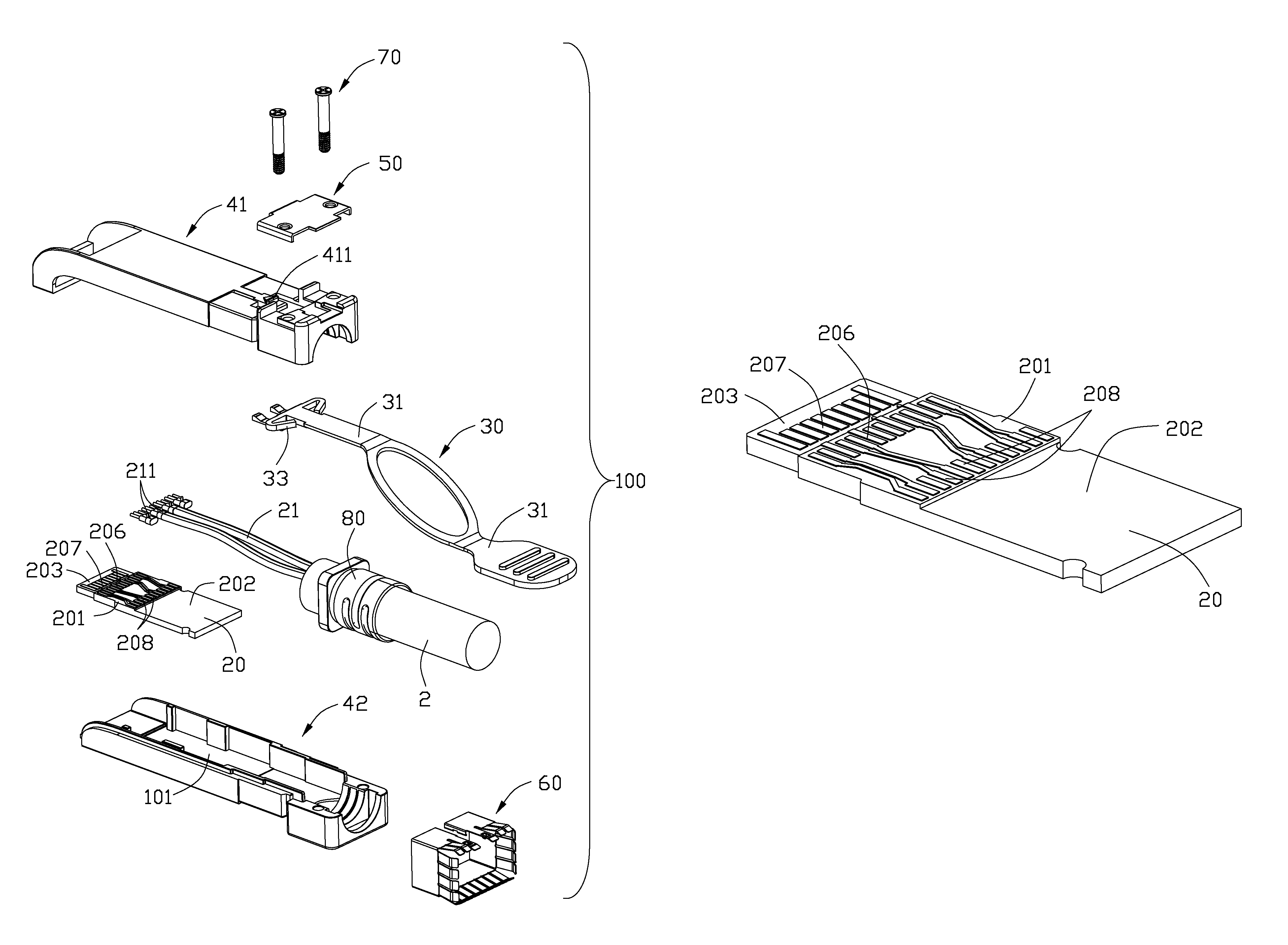
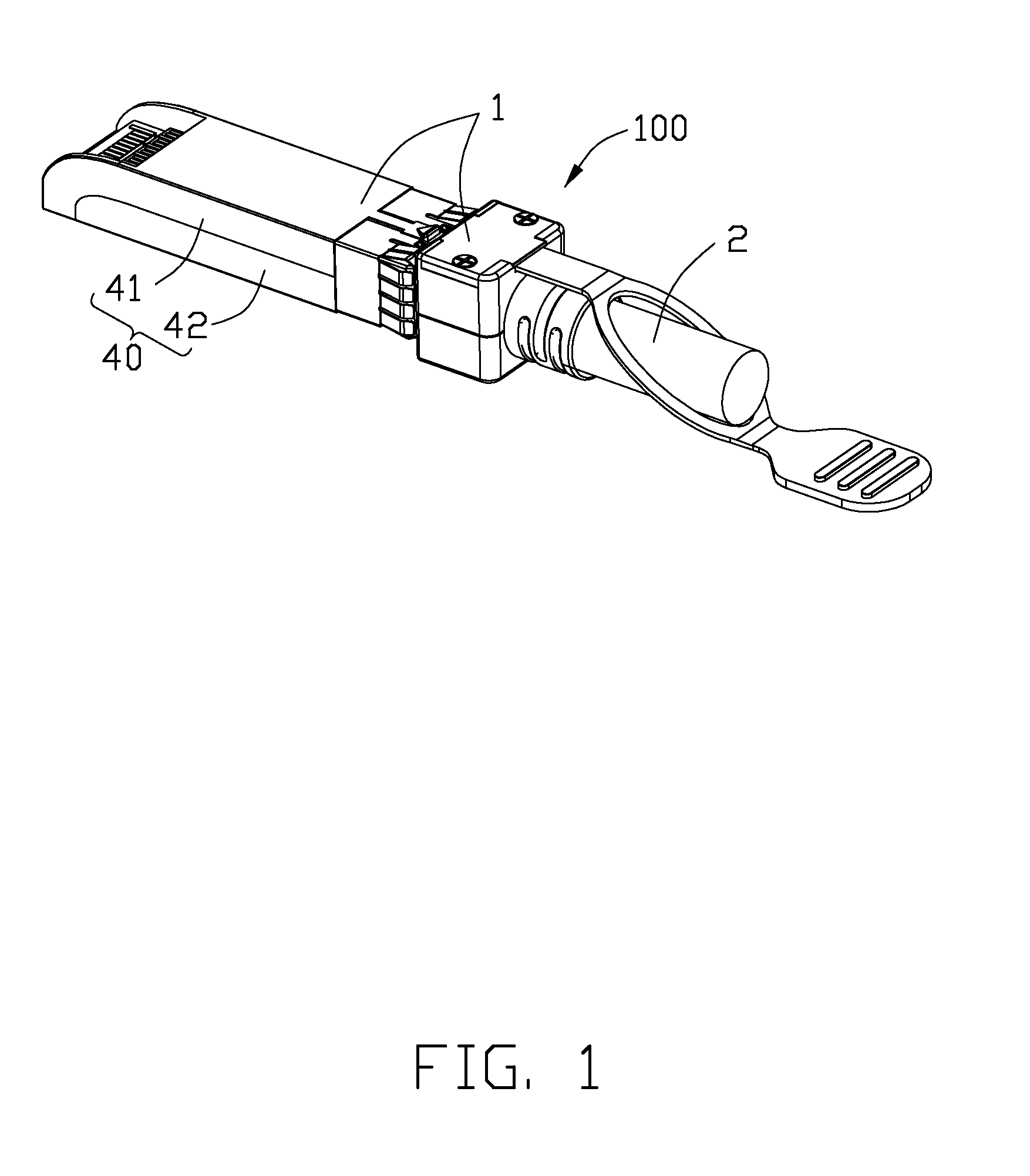
[0015]Referring to FIG. 1, a cable assembly 100 comprises a connector module 1 adapted for mating with a receptacle connector (not shown) and a cable 2 connecting to the connector module 1.

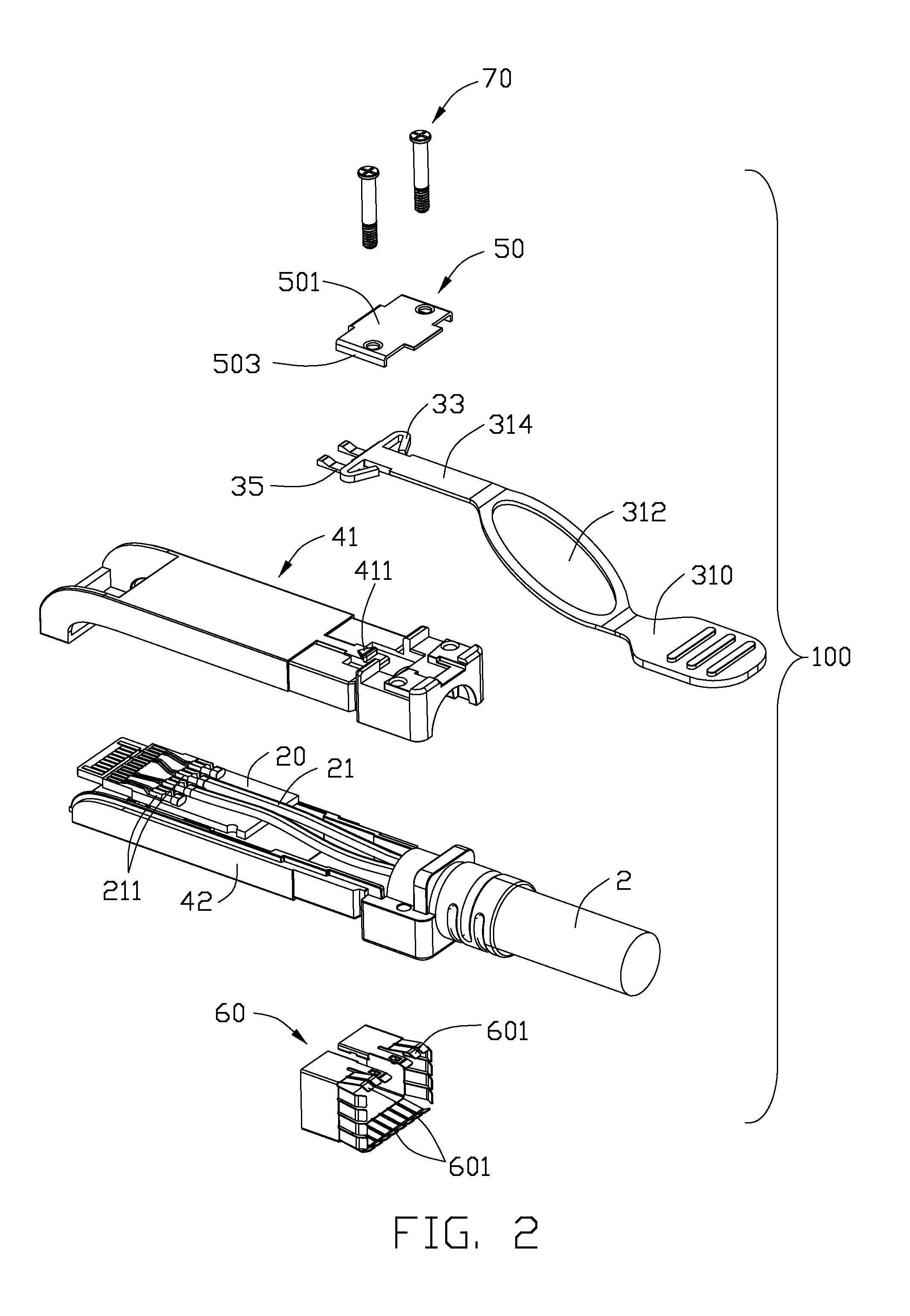
[0016]Referring to FIGS. 2 and 3, the connector module 1 comprises a cover 40 and a circuit board 20 assembled therein. The cover 40 includes a top cover 41, a bottom cover 42 and a cavity 101 formed therebetween. The top cover has a protrusion 411 for locking with the receptacle connector. The connector module 1 further includes a releasing mechanism 30 movable from a latched position to a released position for releasing the protrusion 411.

[0017]The releasing mechanism 30 includes a connection portion 314, an actuating portion 35 formed at the front of the connection portion 314 and an operating portion 310 formed at the end of the connection portion 314 for actuating the releasing mechanism 30. The co...


PUM


Abstract

A cable assembly (100) includes a cover (40) defining a cavity (101), a circuit board (20) assembled in the cavity and including a first surface (201) and a second surface (202) lower than the first surface, and a cable (2) having a jacket (22) and a number of wires (21) shrouded by the jacket. Each wire includes an inner coat (210) and a conductor having a free end (211) exposed outwardly from the inner coat for being soldered to the first surface, with the inner coat disposed on the second surface.

Description

BACKGROUND OF THE INVENTION[0001]1. Field of the Invention[0002]The present invention relates to a cable assembly, and more particularly to a SFP (Small Form-factor Pluggable) cable assembly having a circuit board mounted therein.[0003]2. Description of Related Art[0004]U.S. Pat. No. 7,297,028, issued to Daikuhara on Nov. 20, 2007 discloses a cable connector having a PCB (Printed Circuit Board). A cable has a number of wires soldered to the PCB via a number of soldering joints for transmitting high speed signals. The PCB has a flat top surface and a number of soldering pads formed thereon. Each of the wires includes a conductor and a coat wrapped on the conductor. A front end of the conductor is exposed outwardly from the coat and is bent close to the soldering pad when the conductor is soldered to the PCB. It is hard to solder the conductors to the flat top surface due to a thickness of the coat.[0005]Hence, a cable assembly having an improved circuit board is desired.SUMMARY OF TH...

Claims


Application Information

Patent Timeline
Patent Type & Authority Patents(United States)
CPCH01R9/038H01R13/6658H01R13/502H01R12/515H01R13/65918
Inventor WANG, CHIEN-CHIUNGZHANG, XUE-LIANGZHU, QING-MANZHU, JIAN-JUN
Owner HON HAI PRECISION IND CO LTD
Why Eureka
Try Eureka