Reduction sleeve

a technology of sleeves and sleeves, applied in the field of sleeves, can solve the problems of considerable difficulty for surgeons when using this method, and achieve the effect of reducing the difficulty of surgery

Active Publication Date: 2014-03-04
DEPUY SYNTHES PROD INC
View PDF15 Cites 24 Cited by
  • Summary
  • Abstract
  • Description
  • Claims
  • Application Information

AI Technical Summary

Benefits of technology

[0007]In one exemplary embodiment, the reduction sleeve may include a longitudinal axis, an upper end, a lower end, an outer surface, a channel, and a through-bore extending from the upper end to the lower end, the through bore defining an inner surface. The through-bore being substantially perpendicular to the longitudinal axis and being sized and configured to receive the bone fixation element. The channel being substantially transverse to the longitudinal axis and being substantially aligned with the rod-receiving channel formed in the bone fixation element so that, once the bone fixation element has been inserted into the reduction sleeve, the spinal rod can pass through the channel formed in the reduction sleeve and the rod-receiving channel formed in the bone fixation element. The reduction sleeve preferably further including at least one break-off point or region for facilitating breaking the reduction sleeve into multiple pieces.
[0008]In another exemplary embodiment, the reduction sleeve may include a longitudinal axis, an upper end, a lower end, an outer surface, a channel, and a through-bore extending from the upper end to the lower end, the through-bore defining an inner surface. The through-bore being preferably substantially perpendicular to the longitudinal axis and being sized and configured to receive the bone fixation element. The channel preferably being substantially transverse to the longitudinal axis and defining a pair of spaced apart arms having a top surface so that the top surface of the spaced apart arms formed in the reduction sleeve are sized and configured to extend above the top surface formed in the bone fixation element by a distance A, when the bone fixation element is inserted into the reduction sleeve. The reduction sleeve preferably also including at least one break-off point or region for facilitating breaking the reduction sleeve into multiple pieces.

Problems solved by technology

Surgeons have, however, often encountered considerable difficulty when using this method, due to problems associated with aligning the spinal rod(s) within the rod-receiving channels formed in the heads or body portion of the bone fixation elements.

Method used


Image

  • Reduction sleeve
  • Reduction sleeve
  • Reduction sleeve

Examples


Embodiment Construction

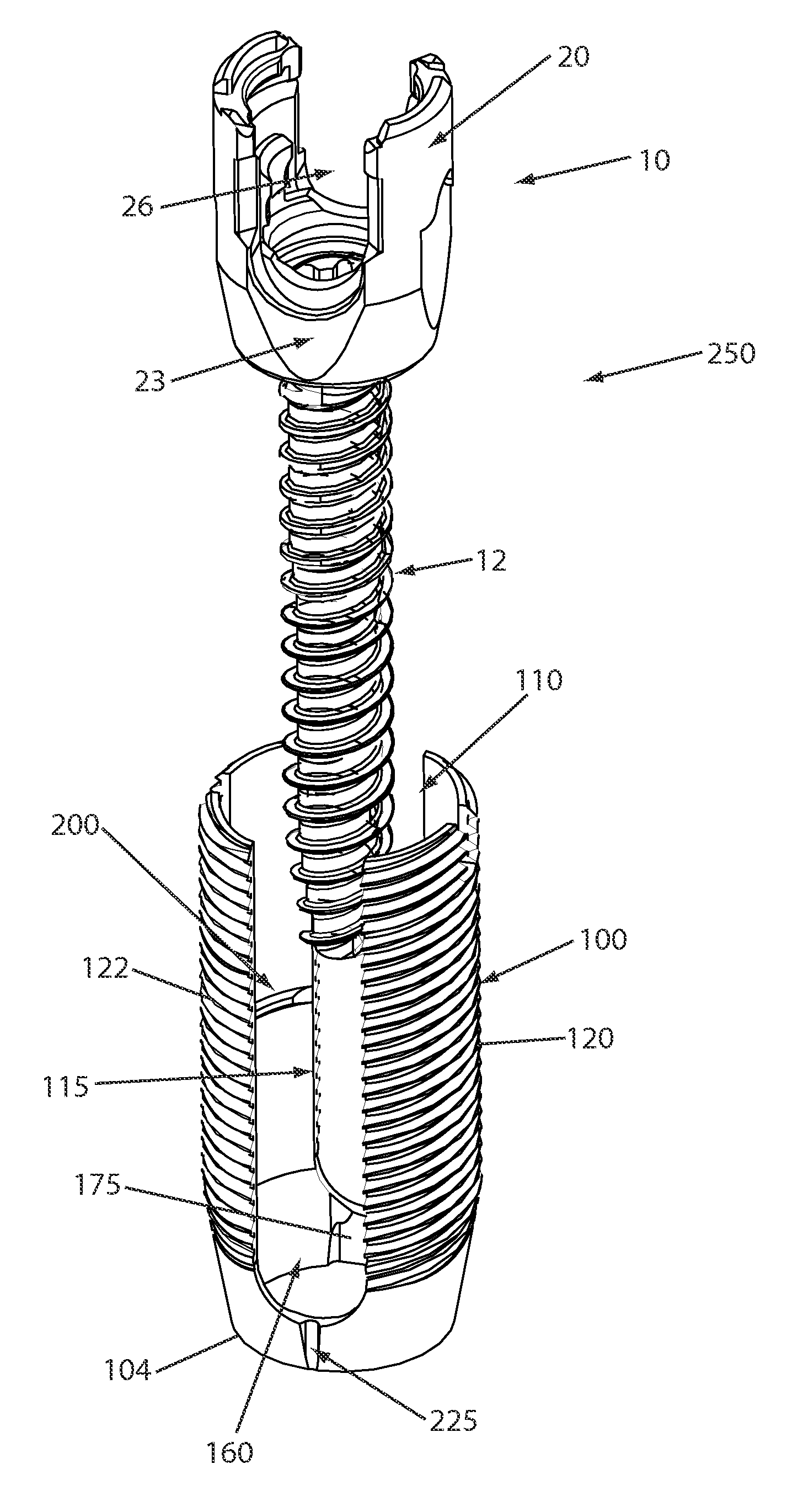
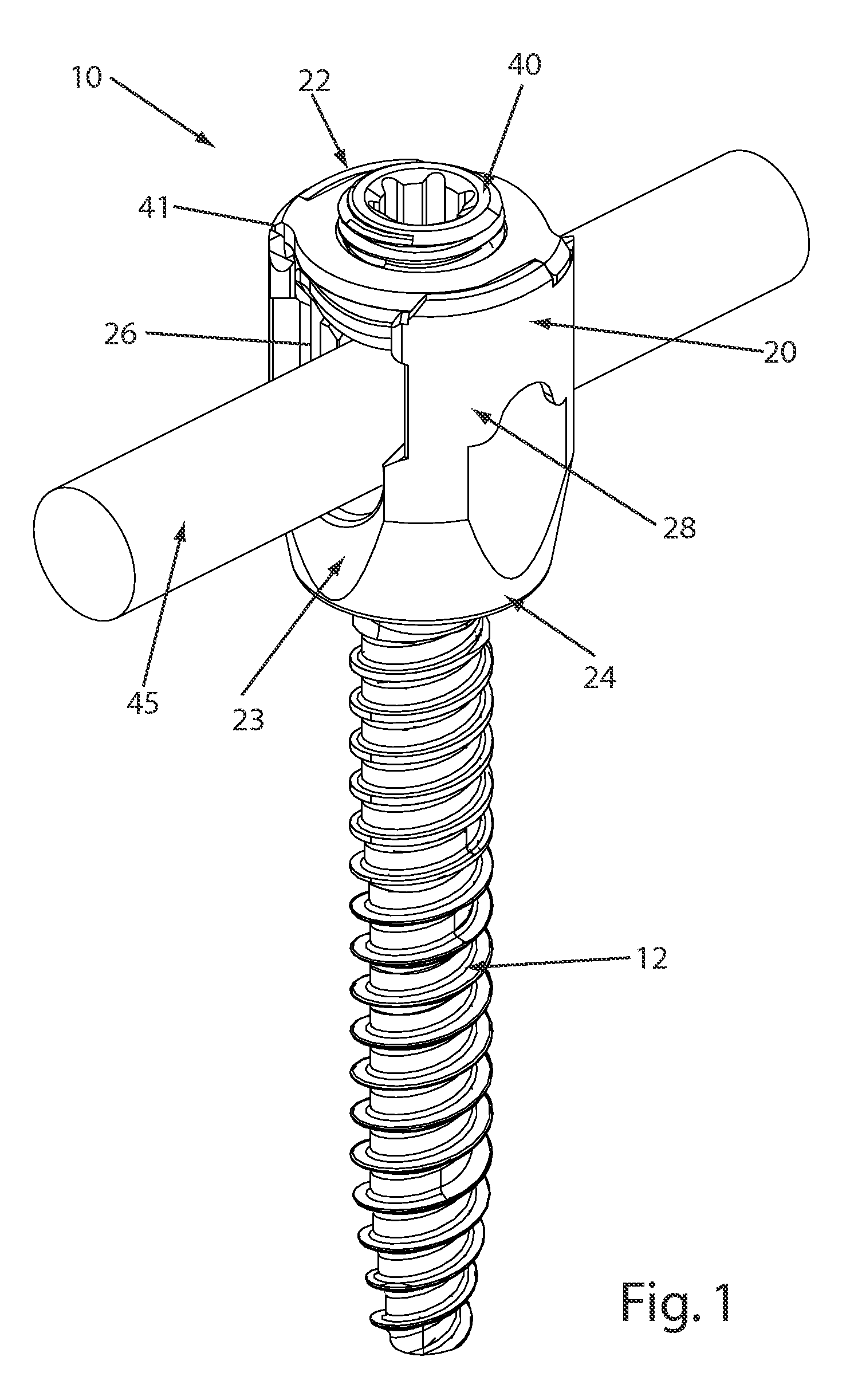
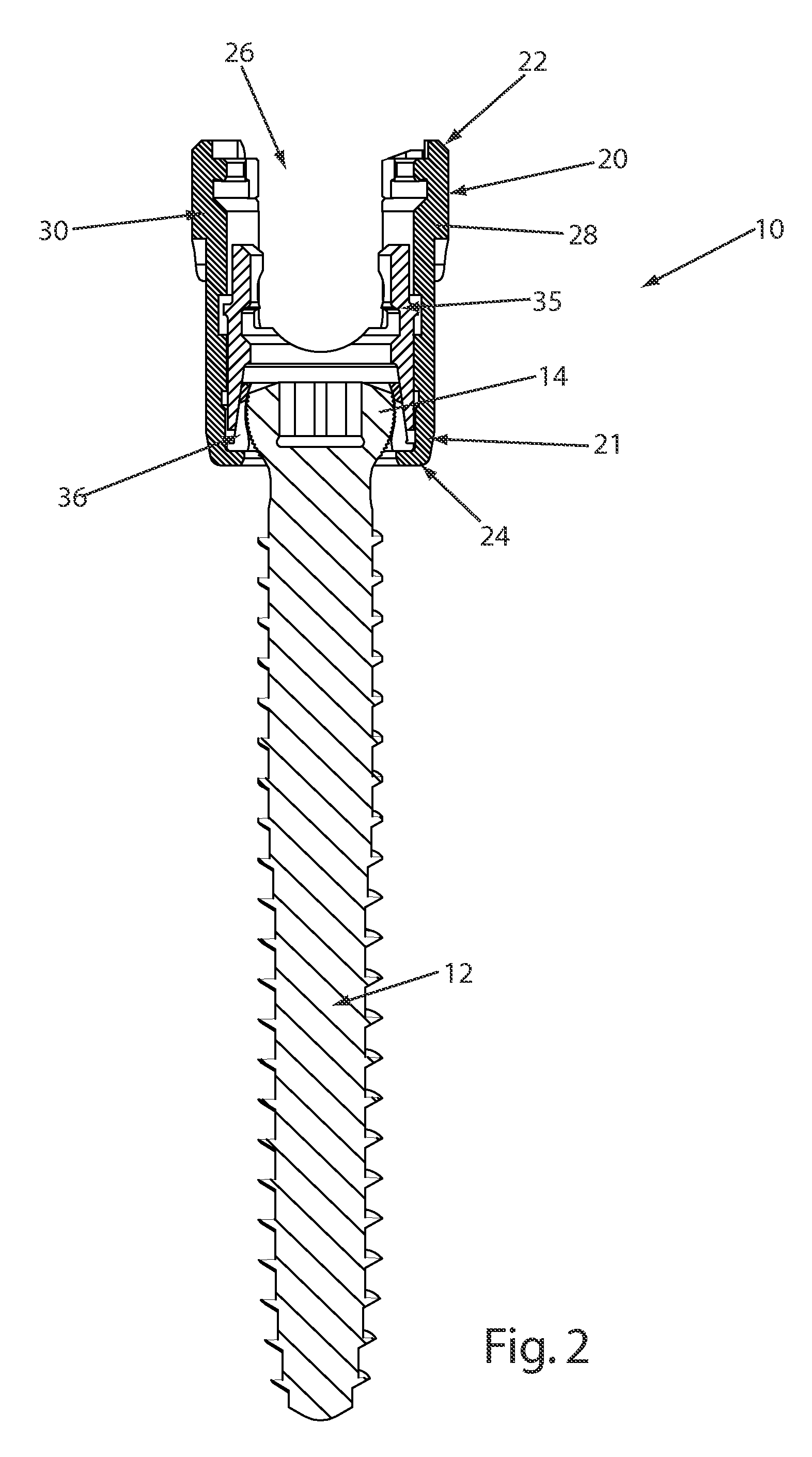
[0038]Certain exemplary embodiments of the invention will now be described with reference to the drawings. In general, such embodiments relate to a reduction sleeve, by way of non-limiting example, a reduction sleeve for use in posterior spinal fixation to facilitate insertion of a longitudinal spinal rod in a rod-receiving channel formed in a bone fixation element. The invention may have other applications and uses and should not be limited to the structure or use described and illustrated. As will be described in greater detail below, the reduction sleeve may include a vertical through-bore sized and configured to receive a bone fixation element and a transverse channel sized and configured to receive a longitudinal spinal rod. The reduction sleeve may also include a break-off point and / or region so that after the longitudinal spinal rod has been inserted in the rod-receiving channel of the bone fixation element, the reduction sleeve can be removed from the patient's body leaving ...


PUM


Abstract

A reduction sleeve for facilitating insertion of a spinal rod into a rod-receiving channel formed in a bone fixation element. The reduction sleeve may include a through-bore sized and configured to receive the bone fixation element and a substantially transverse channel sized and configured to receive the spinal rod. The channel being substantially aligned with the rod-receiving channel formed in the bone fixation element so that, once the bone fixation element has been inserted into the reduction sleeve, the spinal rod can pass through the aligned channels. The reduction sleeve may also include at least one break-off point or region for facilitating breaking and removal of the reduction sleeve once the spinal rod has been clamped into the rod-receiving channel of the bone fixation element. The reduction sleeve may also include a plurality of threads formed thereon for engaging a reduction instrument, an alignment mechanism so that the bone fixation element can only be inserted into the reduction sleeve when the rod-receiving channels are aligned, and an inwardly projecting protrusion formed on the inner surface of the reduction sleeve so that, once inserted, the projection contacts a top surface formed on the bone fixation element.

Description

CROSS REFERENCE TO RELATED APPLICATION[0001]This application claims priority to U.S. provisional patent application Ser. No. 60 / 839,448, filed Aug. 22, 2006, the contents of which is hereby incorporated by reference in its entirety.FIELD OF THE INVENTION[0002]The invention relates to a reduction sleeve, more specifically a reduction sleeve for facilitating insertion of a longitudinal spinal rod into a rod-receiving channel formed in a bone fixation element.BACKGROUND OF THE INVENTION[0003]It is often necessary due to various spinal disorders to surgically correct and stabilize spinal curvatures, or to facilitate spinal fusion. Numerous systems for treating spinal disorders have been disclosed. One known method involves a pair of elongated members, typically spinal rods, longitudinally placed on the posterior spine on either side of spinous processes of the vertebral column. Each rod is attached to various vertebra along the length of the spine by way of vertebra engaging bone fixati...

Claims


Application Information

Patent Timeline
Patent Type & Authority Patents(United States)
IPC IPC(8): A61B17/88
CPCA61B17/7091A61B17/7032A61B17/7074A61B17/7085A61B2017/567
Inventor DEC, BRIANRATHBUN, DAVID S.
Owner DEPUY SYNTHES PROD INC
Why Eureka
Try Eureka