Bone graft distribution system

a bone graft and distribution system technology, applied in the field of bone graft distribution system, can solve the problems of preventing bone graft from being inserted and placed properly, unable to provide a path for bone graft to be inserted, and unable to fill the space surrounding the cage, so as to facilitate graft distribution and facilitate graft distribution

Active Publication Date: 2014-03-04
INTEGRITY IMPLANTS INC
View PDF114 Cites 83 Cited by
  • Summary
  • Abstract
  • Description
  • Claims
  • Application Information

AI Technical Summary

Benefits of technology

[0023]In some embodiments, each plurality of proximal top connector elements and proximal bottom connector elements are proximal struts configured in an at least substantially parallel alignment in the expanded state and the collapsed state; and, each plurality of distal top connector elements and distal bottom connector elements are distal struts configured in an at least substantially parallel alignment in the expanded state and the collapsed state. In some embodiments, the proximal top struts are configured monolithically integral to the first top beam and the second top beam and adapted to flex toward the distal top struts during collapse; and, the distal top struts are configured monolithically integral to the first top beam and the second top beam and adapted to flex toward the proximal top struts during collapse. Likewise, in some embodiments, the proximal bottom struts are configured monolithically integral to the first bottom beam and the second bottom beam and adapted to flex toward the distal bottom struts during collapse; and, the distal bottom struts are configured monolithically integral to the first bottom beam and the second bottom beam and adapted to flex toward the proximal bottom struts during collapse. And, in these embodiments, the top and bottom of the laterovertically-expanding frame are each configured to open a graft distribution window upon expansion to facilitate graft distribution within the intervertebral space.
[0024]In some embodiments, the central beam further comprises a first side graft port and a second side graft port. In these embodiments, each plurality of proximal connector elements can be configured as proximal struts in an at least substantially parallel alignment in the expanded state and the collapsed state; and, each plurality distal connector elements are distal struts can be configured in an at least substantially parallel alignment in the expa

Problems solved by technology

Unfortunately, therein lies a problem solved by the teachings provided herein.
Currently available systems can be problematic in that the methods of introducing the fusion cage and bone graft material leaves pockets in regions of the intervertebral space that are not filled with bone graft material, regions in which fusion is desired for structural support.
These pockets can create a premature failure of the fused intervertebral space due to forces that are distributed through the regions containing the pockets, for example, when the patient stands and walks.
However, this makes it difficult to insert and position properly.
Unfortunately, these types of devices have the typical graft distribution problem discussed ab

Method used


Image

  • Bone graft distribution system
  • Bone graft distribution system
  • Bone graft distribution system

Examples


Embodiment Construction

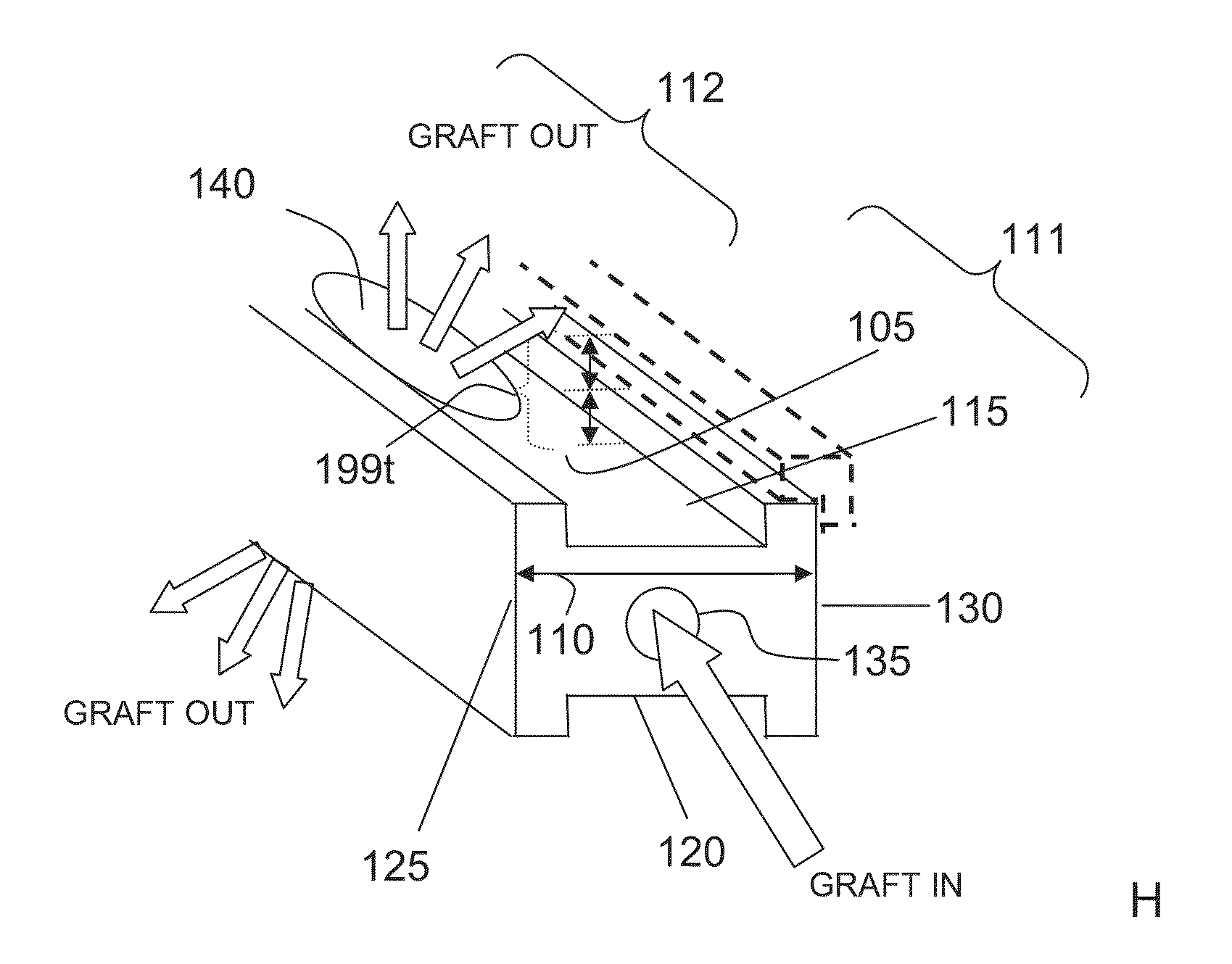
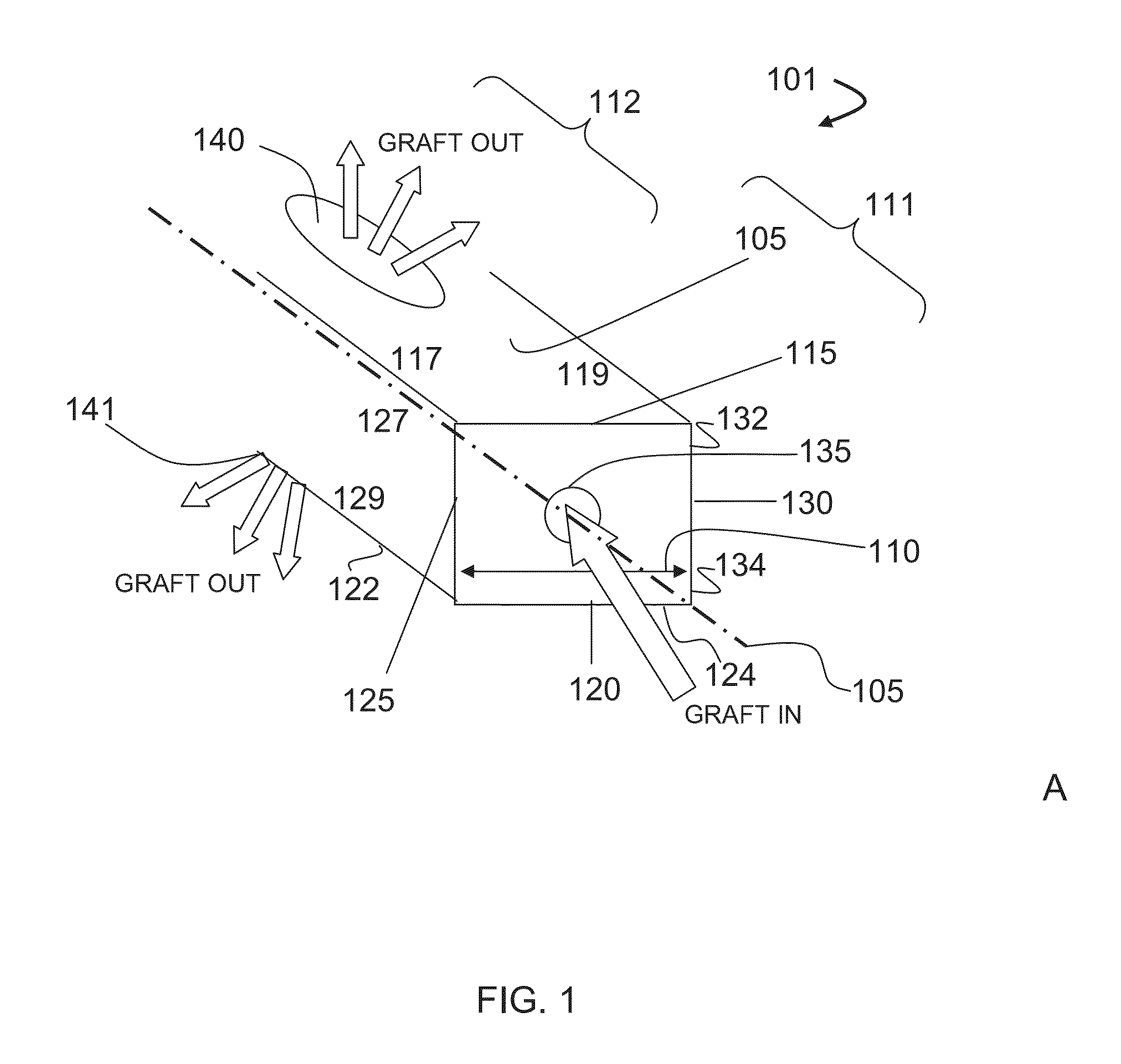
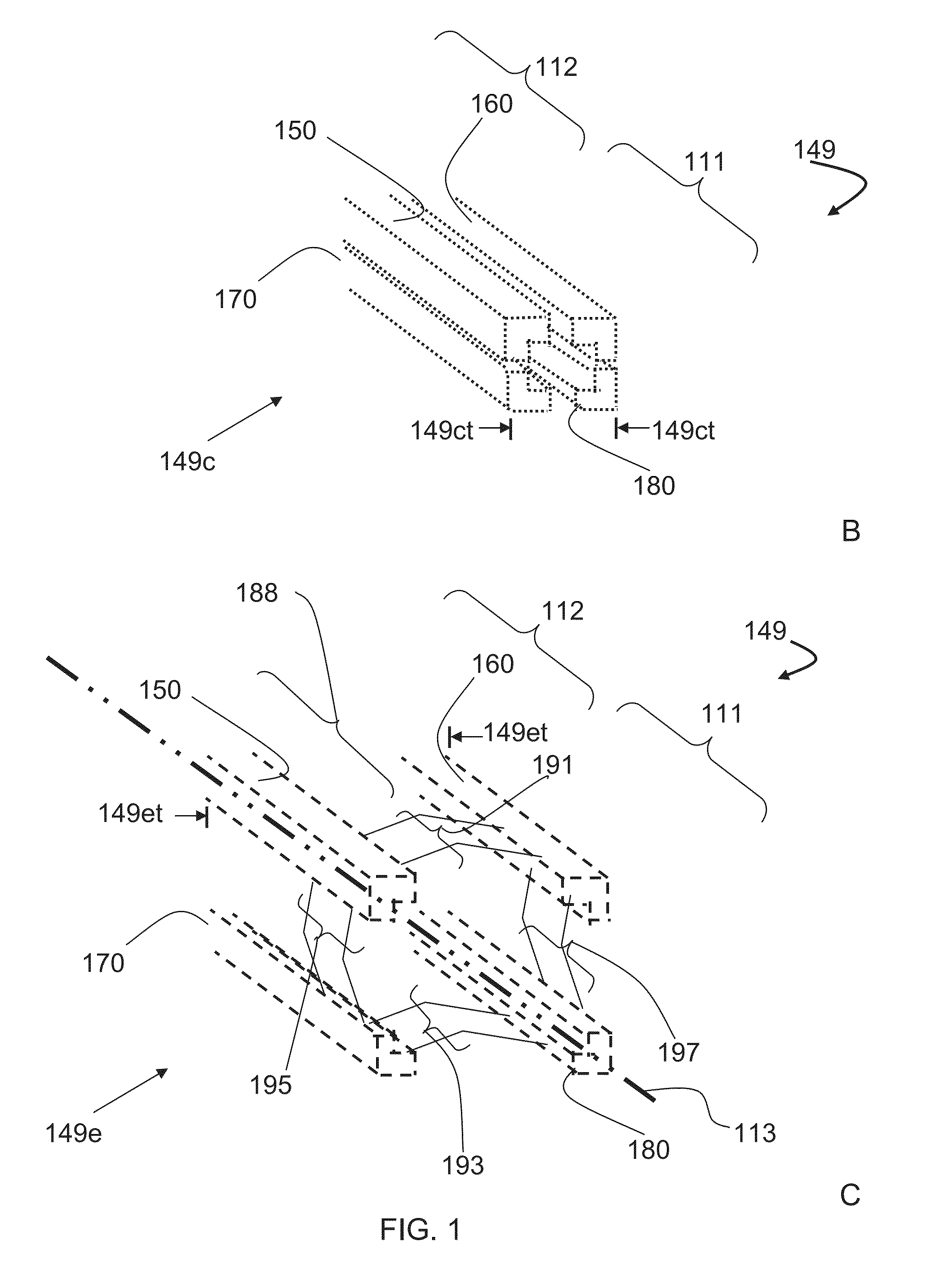
[0043]The teachings herein are generally directed to a system for distributing bone graft material in an intervertebral disc space. The graft distribution systems can have, for example, a central beam having a proximal portion having an end, a grafting portion having a top and a bottom, a distal portion having a end, a central beam axis, a graft distribution channel having an entry port at the end of the proximal portion, a top exit port at the top of the grafting portion, and a bottom exit port at the bottom of the grafting portion. These systems can also include a laterovertically-expanding frame having a lumen, a first top beam, a second top beam, a first bottom beam, and a second bottom beam, each having a proximal portion and a distal portion, and each operably connected to each other at their respective proximal portions and distal portions with connector elements to form the laterovertically-expanding frame that is operable for a reversible collapse from an expanded state int...


PUM

PropertyMeasurementUnit
Lengthaaaaaaaaaa
Lengthaaaaaaaaaa
Lengthaaaaaaaaaa

Abstract

A system for distributing bone graft material in an intervertebral disc space is provided having a central beam having a proximal portion having an end, a grafting portion having a top and a bottom, a distal portion having a end, a central beam axis, a graft distribution channel having an entry port at the end of the proximal portion, a top exit port at the top of the grafting portion, and a bottom exit port at the bottom of the grafting portion. These systems can also include a laterovertically-expanding frame operable for a reversible collapse from an expanded state into a collapsed state. The expanded state, for example, can be configured to have an open graft distribution window that at least substantially closes upon the reversible collapse.

Description

CROSS-REFERENCE TO RELATED APPLICATIONS[0001]This application claims the benefit of U.S. Provisional Application No. 61 / 737,054, filed Dec. 13, 2012.BACKGROUND[0002]1. Field of the Invention[0003]The teachings herein are directed to a system for distributing bone graft material in an intervertebral disc space.[0004]2. Description of the Related Art[0005]Bone grafts are used in spinal fusion, for example, which is a technique used to stabilize the spinal bones, or vertebrae, and a goal is to create a solid bridge of bone between two or more vertebrae. The fusion process includes “arthrodesis”, which can be thought of as the mending or welding together of two bones in a spinal joint space, much like a broken arm or leg healing in a cast. Spinal fusion may be recommended for a variety of conditions that might include, for example, a spondylolisthesis, a degenerative disc disease, a recurrent disc herniation, or perhaps to correct a prior surgery.[0006]Bone graft material is introduced ...

Claims


Application Information

Patent Timeline
IPC IPC(8): A61F2/44
CPCA61F2002/30777A61F2310/00071A61F2002/30019A61F2/4684A61F2002/30779A61F2/44A61F2002/30598A61F2002/4435A61F2002/444A61F2/441A61F2310/00023A61F2/30965A61F2002/2835A61F2310/00029A61F2/447A61F2002/30556A61F2002/30579A61F2310/00053A61F2310/00011A61F2/442A61F2310/00179A61F2002/30785A61F2002/30581A61F2/4611A61F2310/00047A61F2310/00293A61F2002/2817A61F2002/30594A61F2002/30593
Inventor TO, JOHNFLYNN, JOHN J.BIRKMEYER, PAUL J.
Owner INTEGRITY IMPLANTS INC
Why Eureka
Try Eureka