
Minimal access tool

a tool and minimal access technology, applied in the field of minimal access tools, can solve the problems of limiting the user's ability to fully exploit the enhanced dexterity capability of the tool, increasing the frequency and complexity of minimal access surgical (mis) and other minimal access procedures, and non-intuitive control of the do

Active Publication Date: 2014-03-11
RGT UNIV OF MICHIGAN
View PDF39 Cites 63 Cited by
  • Summary
  • Abstract
  • Description
  • Claims
  • Application Information

AI Technical Summary

Problems solved by technology

Minimally invasive surgical (MIS) and other minimal access procedures are increasing in frequency and becoming more complex, thus demanding improvements in technology to meet the needs of surgeons.
While these mechanical hand-held tools are inherently capable of force feedback, and the newer tools are capable of enhanced dexterity given their extra two DoF, they present non-intuitive DoF control (input motion to output motion mapping) schemes that limit user's ability to fully exploit the tool's enhanced dexterity capability.
In addition, large size, high cost, and limited large-scale maneuverability also reduce the overall functionality of such robotic systems.
Therefore, most existing multiple DoF tools lack the design characteristics to allow for enhanced dexterity as well as desired functionality in a cost effective, compact package.
In particular, multiple DoF tools that allow for wrist-like rotations of the tool tip manipulator are important to meet the needs of modern minimal access and MIS procedures, but are not effective unless comfortable, ergonomic, and intuitive control of these additional DoF are ensured.

Method used


Image

  • Minimal access tool
  • Minimal access tool
  • Minimal access tool

Examples


Embodiment Construction

[0029]As required, detailed embodiments of the present invention are disclosed herein; however, it is to be understood that the disclosed embodiments are merely exemplary of the invention that may be embodied in various and alternative forms. The figures are not necessarily to scale, and some features may be exaggerated or minimized to show details of particular components. Therefore, specific structural and functional details disclosed herein are not to be interpreted as limiting, but merely as a representative basis for teaching one skilled in the art to variously employ the present invention.

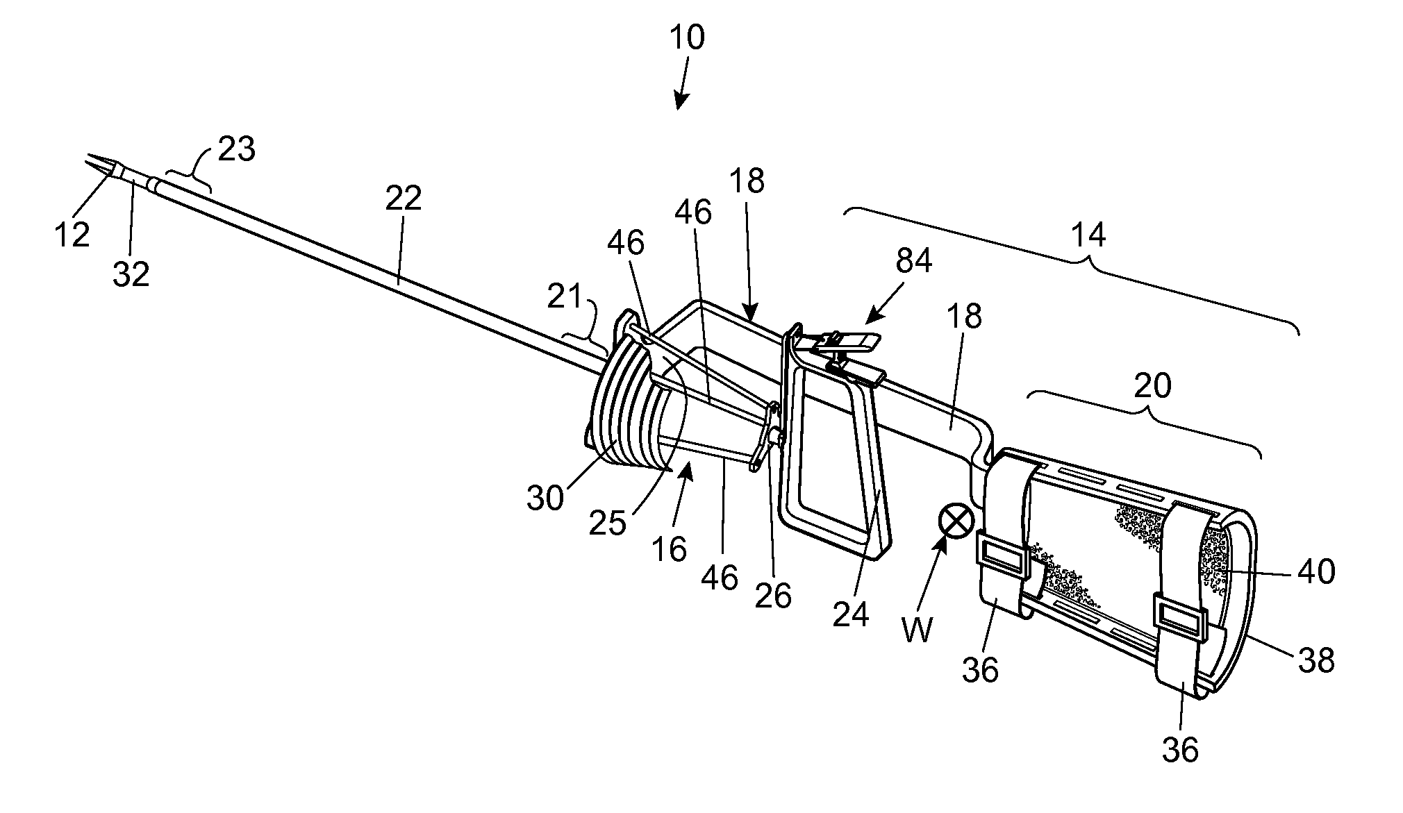
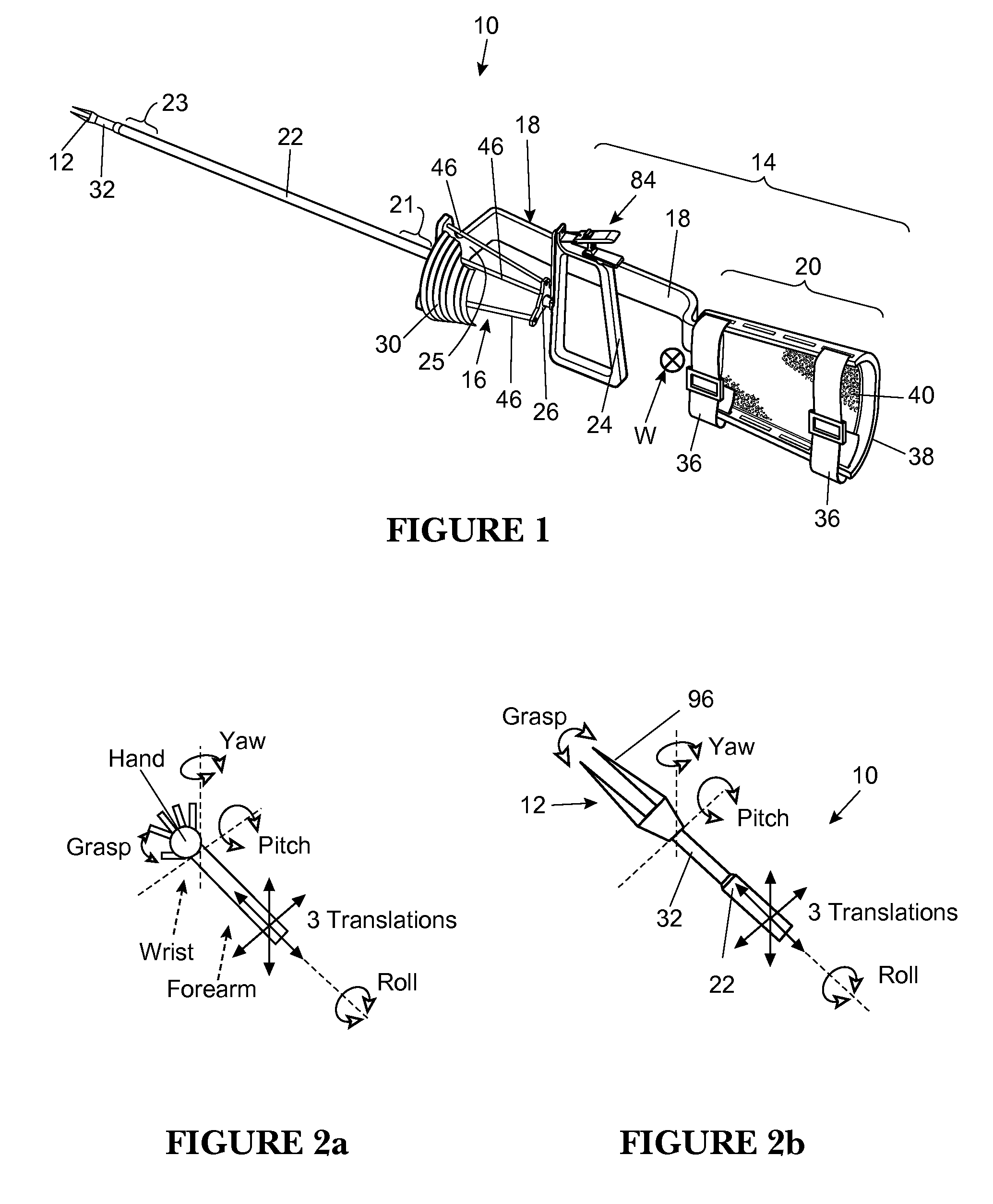
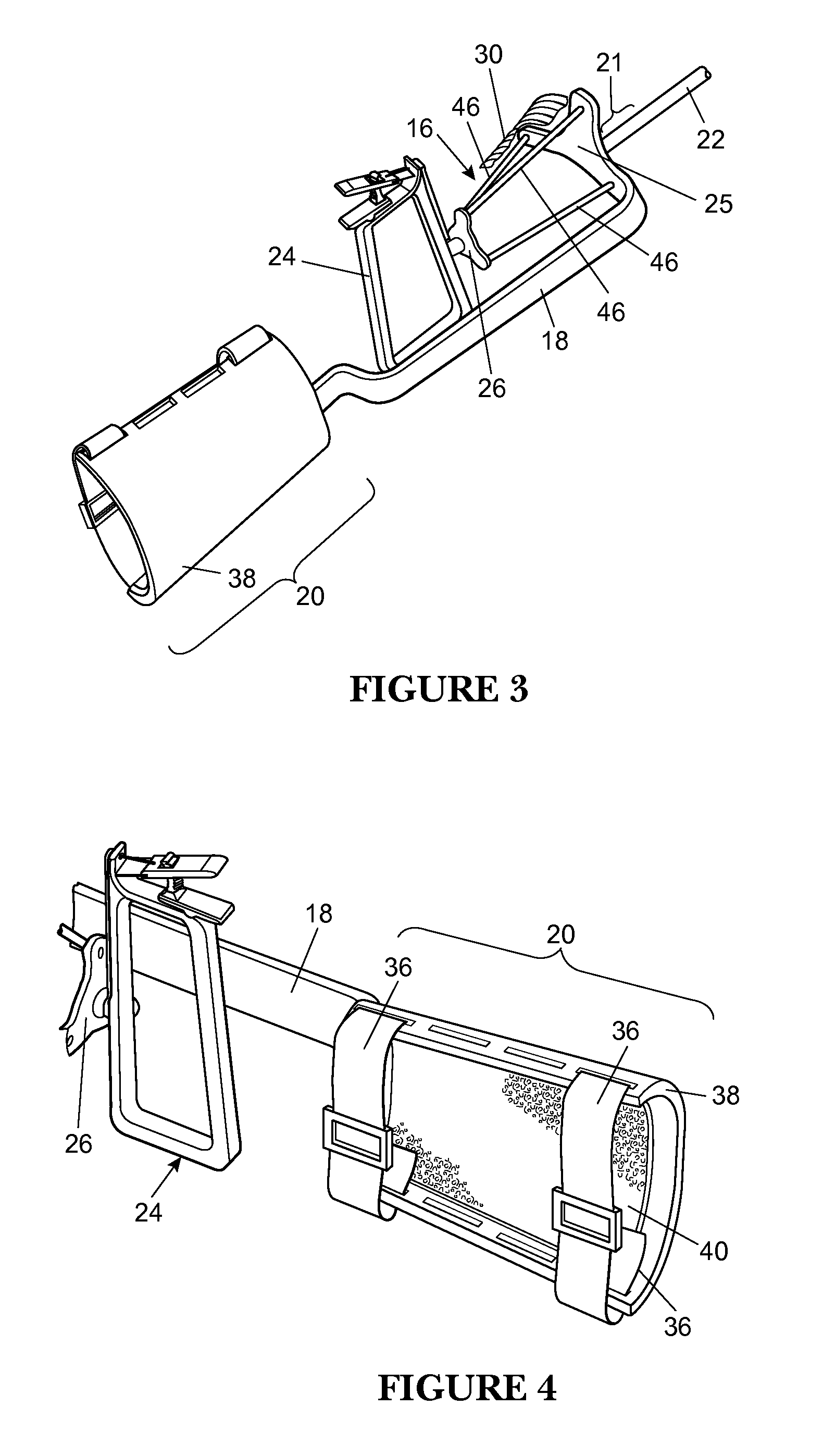
[0030]The present invention provides a high-dexterity, multi-DoF, minimal access tool capable of intuitive actuation for use in MIS, endoscopy, or other interventions. With reference to the drawings, a tool in accordance with the present invention is designated generally by reference numeral 10 and may provide the following functionality. First, six DoF may be provided at an end effector 12, ...


PUM


Abstract

A minimal access tool includes a frame arranged to be attached to an arm of a user, a tool shaft having a proximal end and a distal end, where the tool shaft proximal end is connected to the frame. The tool further includes an input joint having a first end connected to the frame and a second end arranged to receive user input, the input joint including a virtual center-of-rotation (VC) mechanism which provides a center of rotation that generally coincides with a wrist joint of the user. An output joint is connected to the tool shaft distal end, where the output joint is coupled to the input joint via a mechanical transmission connected therebetween to correlate motion of the input joint to motion of the output joint.

Description

CROSS-REFERENCE TO RELATED APPLICATIONS[0001]This application is the United States National Phase under 35 USC 371 of International Patent Application No. PCT / US2009 / 040353, filed Apr. 13, 2009, which claims the benefit of the filing date of U.S. provisional application Ser. No. 61 / 044,168 filed Apr. 11, 2008, which is incorporated by reference herein.BACKGROUND OF THE INVENTION[0002]1. Field of the Invention[0003]This invention relates to a minimal access tool, such as for surgery, endoscopy, or other interventions.[0004]2. Background Art[0005]Minimally invasive surgical (MIS) and other minimal access procedures are increasing in frequency and becoming more complex, thus demanding improvements in technology to meet the needs of surgeons. In these procedures, generally thin tools are inserted into the body through ports. Motion input from the user, such as a surgeon, is transferred via the tool to the motion of a manipulator attached to the tool's tip inside the patient's body. This...

Claims


Application Information

Patent Timeline
Patent Type & Authority Patents(United States)
IPC IPC(8): A61B19/00
CPCA61B2017/2937A61B2017/00323A61B2017/00464A61B2019/2242A61B2017/00442A61B2017/2917A61B2017/2939A61B2017/00424A61B2019/2288A61B2017/2931A61B2017/2929A61B17/2909A61B2017/2944A61B2019/2296A61B2019/2238A61B19/22A61B34/75A61B34/70A61B34/71A61B2034/306A61B34/77
Inventor AWTAR, SHORYANIELSEN, JENSTRUTNA, TRISTANMANSFIELD, ANDREWABANI, ROSAGEIGER, JAMESQUIGLEY, PATRICK
Owner RGT UNIV OF MICHIGAN
Learn More