Contactless liquid level sensor

a liquid level sensor and contactless technology, applied in liquid/fluent solid measurement, instruments, machines/engines, etc., can solve the problems of reducing the friction resistance in a dramatic way, and achieve the effect of reducing friction resistance, ensuring detection accuracy, and stable positional relation

Active Publication Date: 2014-03-18
YAZAKI CORP
View PDF15 Cites 9 Cited by
  • Summary
  • Abstract
  • Description
  • Claims
  • Application Information

AI Technical Summary

Benefits of technology

[0015]The invention has been accomplished in view of the above circumstances. An object of the invention is to provide a contactless liquid level sensor capable of preventing a drop in the detection accuracy caused by wear of the central shaft of a frame where a magnet holder and the magnet are fitted to each other in the course of prolonged use.
[0018]With the contactless liquid level sensor of the configuration (1), a fitting hole in the magnet holder made of a resin material and the central shaft of the frame made of a resin material are fitted to each other via a metallic rotary support. Direct contact of resin between a fitting hole and a central shaft is avoided and the central shaft and the fitting hole are slidable via a rotary support. This offers sliding by a contact between a metal and resin, which dramatically reduces the friction resistance compared with a case where resin-made fitting hole and central shaft are in direct sliding on each other. This suppresses wear of the fitting hole and the central shaft. This also stabilizes the relative position of the magnet holder with respect to the central shaft and maintains constant detection accuracy despite prolonged use.
[0020]With the contactless liquid level sensor of the configuration (2), the rotary support includes a locking part at one end and the locking part is engaged and fitted to an engaging part arranged on the frame. This restricts relative rotation of the rotary support with respect to the central shaft. The only sliding parts of the contactless liquid level sensor in operation are the rotary support and the fitting hole, which further suppresses possible wear. The influence of a gap between the central shaft and the rotary support on the position accuracy of the magnet holder is eliminated, thus further enhancing the detection accuracy.
[0022]With the contactless liquid level sensor of the configuration (3), it is possible to flexibly change the shape of the guard through piece division for a mold, thus setting a restriction angle for relative rotation of the rotary support with respect to the central shaft.
[0024]With the contactless liquid level sensor of the configuration (4), it is possible to further restrict the relative rotation of the rotary support with respect to the central shaft.
[0025]With the contactless liquid level sensor according to the invention, the central shaft is inserted into the fitting hole in the magnet holder via a rotary support. The resin material of the fitting hole and the resin material of the central shaft slide and rotate via the rotary support without direct contact therebetween, which suppresses wear of the fitting hole and the central shaft. This prevents the magnet holder from being inclined with respect to the central shaft to maintain stable positional relation and constantly keep certain detection accuracy.

Problems solved by technology

This offers sliding by a contact between a metal and resin, which dramatically reduces the friction resistance compared with a case where resin-made fitting hole and central shaft are in direct sliding on each other.

Method used


Image

  • Contactless liquid level sensor
  • Contactless liquid level sensor
  • Contactless liquid level sensor

Examples


Embodiment Construction

[0036]A preferable embodiment according to the invention will be detailed based on the accompanying drawings.

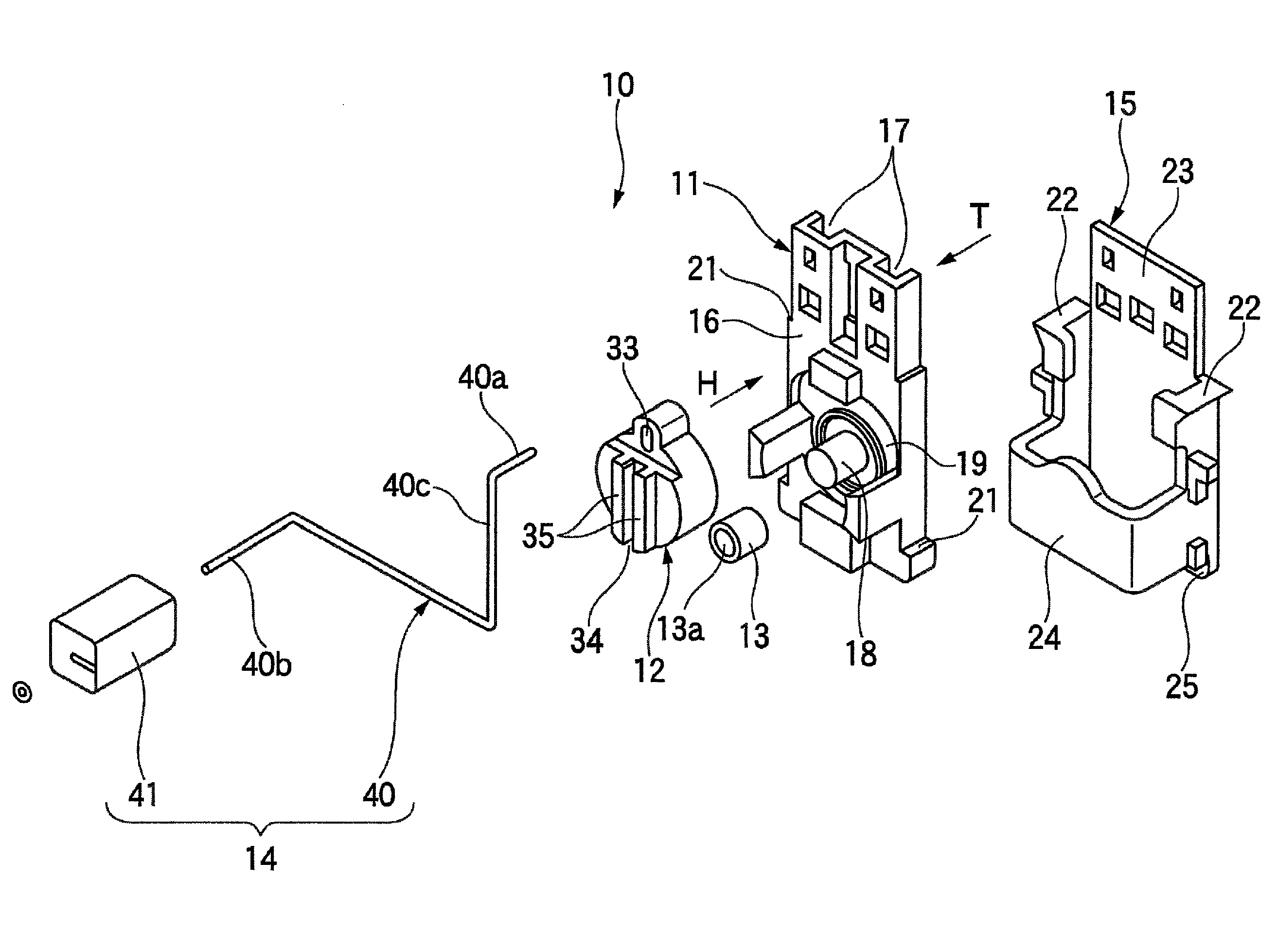
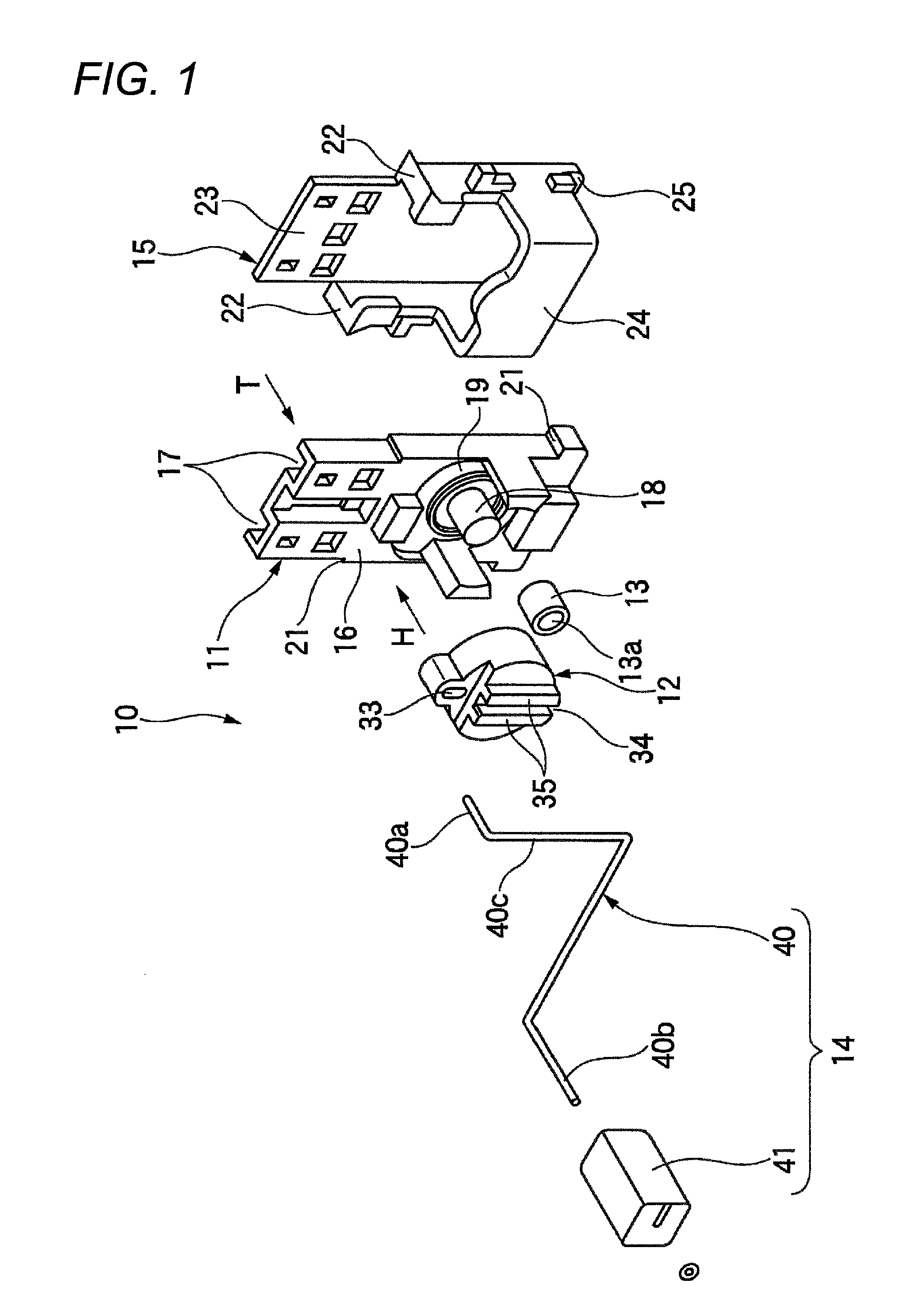
[0037]FIG. 1 is an exploded perspective view of a contactless liquid level sensor according to an embodiment of the invention. FIG. 2 is a cross-sectional view of the attaching state of the central shaft of a frame and a rotary support to the fitting hole in a magnet holder shown in FIG. 1.

[0038]As shown in FIG. 1, a contactless liquid level sensor 10 according to this embodiment is designed to detect the liquid level of a liquid such as gasoline and includes a frame 11, a magnet holder 12, a rotary support 13, a float part 14, and a cover 15.

[0039]The frame 11 according to this embodiment is formed by a general molding method such as injection molding by using an appropriate resin material such as POM or PPS. The frame 11 includes a frame body 16 formed into a thin box shape. One surface (rear surface on the T side) of the frame body 16 has an opening to form a pair of lead ...


PUM


Abstract

The present invention is to prevent a drop in the detection accuracy caused by wear of the central shaft of a frame where a magnet holder and the magnet are fitted to each other in the course of prolonged use. A contactless liquid level sensor includes: a magnet holder which includes a resin holder body having an inner circumferential surface for defining a fitting hole and a magnet accommodated inside the holder body along the inner circumferential surface; a resin frame including a frame body, a central shaft protruding from the frame body, and a magnetic-electric converter accommodated inside the central shaft; a float arm including one end fixed to the magnet holder and the other end attached to a float vertically moving in accordance with a liquid level; and a metallic rotary support including a hollow cylindrical part arranged between the inner circumferential surface of the holder body and an outer circumferential surface of the central shaft. When the magnet holder rotates about the central shaft in accordance with the liquid level, a magnetic flux density passing through the magnetic-electric converter is varied thereby detecting a variation in the liquid level.

Description

TECHNICAL FIELD[0001]The present invention relates to a contactless liquid level sensor, and in particular, to a contactless liquid level sensor that prevents a drop in the detection accuracy caused by wear of a slid parts in a contactless liquid level sensor in order to enhance the durability.BACKGROUND ART[0002]An example of a known contactless liquid level sensor (for example, Patent Reference 1) will be described. FIG. 5 is a vertical cross-sectional view of a known contactless liquid level sensor. FIG. 6 is a perspective view showing the positional relation between a magnetic-electric conversion element, a magnet and a stator extracted from the contactless liquid level sensor shown in FIG. 5. FIG. 7 is an enlarged vertical cross-sectional view of a key point showing a known contactless liquid level sensor where a magnet chamber cover is attached to a magnet chamber.[0003]As shown in FIG. 5, a known contactless liquid level sensor 100 is arranged so that a sensor housing 110 mad...

Claims


Application Information

Patent Timeline
Patent Type & Authority Patents(United States)
IPC IPC(8): G01F23/30
CPCG01F23/38
Inventor FUKUHARA, TOSHIAKI
Owner YAZAKI CORP
Why Eureka
Try Eureka