Drivable device for compacting a soil layer structure and method for ascertaining a layer modulus of elasticity of an uppermost layer of this soil layer structure

a soil layer structure and driving device technology, applied in the direction of in situ soil foundation, blast furnace components, sonic/ultrasonic/infrasonic waves, etc., can solve the problem of inability to precisely detect the moduli of elasticity of the respective layers, the loosening of the compacted soil layer structure, and the excess strain of the compaction devi

Active Publication Date: 2014-03-18
BOMAG
View PDF10 Cites 31 Cited by
  • Summary
  • Abstract
  • Description
  • Claims
  • Application Information

AI Technical Summary

Benefits of technology

[0011]The object of the present invention is therefore to specify a device for compacting a soil layer structure of the above-mentioned type, which allows the rapid and cost-effective detection or monitoring of a layer modulus of elasticity of the soil layer structure and in particular an uppermost layer.
[0023]The first and at least the second detection means or devices preferably have at least one geophone or similar deformation meter, via which reflected waves because of the introduced load pulses are detectable in particular in the soil layer structure. In this way, very precise detection of the respective values of the depression trough is possible.
[0026]The first and at least second detection means or devices are preferably implemented so that they allow a precise detection of the deformations caused by the load introduction pulses in the respective areas. A detection can be performed using all methods and devices known from the prior art. It is thus also possible to perform a detection via the vibration means itself and by its settling movements during the vibration procedure. A very simple detection of the first and at least second values is possible, for example, by means of an electromechanical transducer implemented as a geophone, which converts the soil vibrations into analog voltage signals.
[0029]It is possible to situate the first detection means or device on the vibration roller or its bearing unit, in particular on a vibrating drum of the vibration roller. A precise detection of the first value in the load introduction area and in particular the load center of the load introduction area can be performed very simply in this way.
[0033]It is thus fundamentally possible by means of the drivable device according to the present invention and the method according to the present invention to perform a carrying capacity study, in particular of an uppermost layer of a soil layer structure, during a compaction process of a soil layer structure. A soil compaction machine, as is known from the prior art, is thus preferably equipped with the detection devices according to the present invention and further conversion and regulating units required for this purpose in order to perform a method similar to the method of the carrying capacity study using the “falling weight deflectometer”. It is also possible in this context to offer a drivable device which allows a soil compaction machine to be equipped later with the above detection means or means for detecting a layer modulus of elasticity of an uppermost layer of a layer structure.

Problems solved by technology

After achieving the maximum compaction, further compaction of the soil layer structure is no longer necessary or is even counterproductive, because it results in renewed loosening of the compacted soil layer structure and excess strain of the compaction device.
However, it is problematic in this case that because of the structure of the soil composed of different layers, precise detection of the moduli of elasticity of the respective layers, i.e., the layer moduli of elasticity, is only imprecisely possible, since the moduli of elasticity of the individual layers, in particular unbound layers, mutually influence one another.
However, this method has the disadvantage that the ascertainment of the layer moduli of elasticity using the FWD is very time-consuming and no further work can be performed on the soil layer structures during the measurement.
The values obtained by the FWD are also only available to a soil compaction device, and in particular a road roller, after a time delay, so that a compaction-controlled method or the compaction-controlled soil compaction is only possible with difficulty.

Method used


Image

  • Drivable device for compacting a soil layer structure and method for ascertaining a layer modulus of elasticity of an uppermost layer of this soil layer structure
  • Drivable device for compacting a soil layer structure and method for ascertaining a layer modulus of elasticity of an uppermost layer of this soil layer structure
  • Drivable device for compacting a soil layer structure and method for ascertaining a layer modulus of elasticity of an uppermost layer of this soil layer structure

Examples


Embodiment Construction

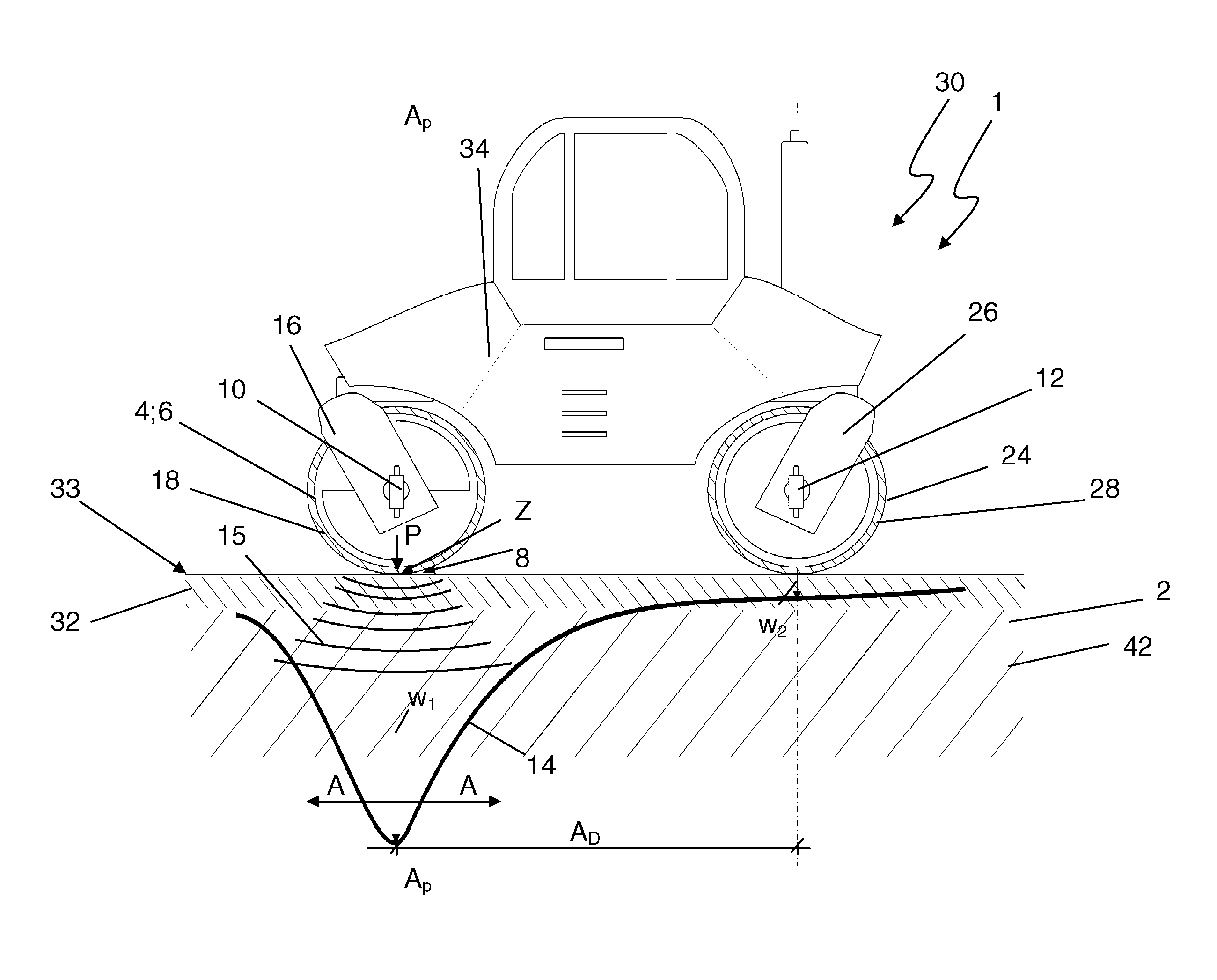
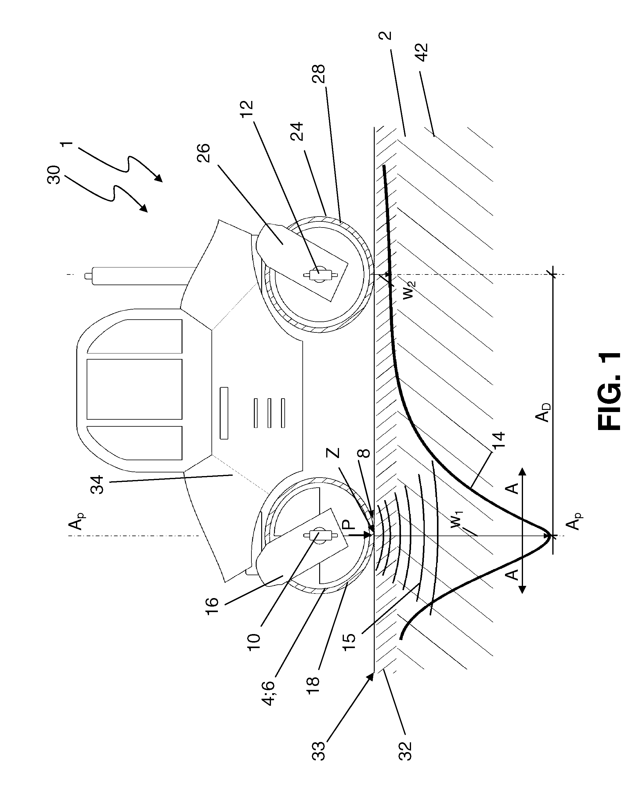
[0038]FIG. 1 shows an illustration of an embodiment of a drivable device 1 according to the present invention for compacting a soil layer structure. The device 1 is implemented here as a self-propelled road roller and in particular as a compactor 30. It comprises a vibration means or device implemented as a vibration roller 6, which is connected via a bearing unit 16 to a main body 34 of the compactor 30. A static roller 24 is associated via a further bearing unit 26, so that the compactor 30 is drivable via the two rollers 6, 24.

[0039]In contrast to the static roller 24, in the case of which compaction of a soil structure 2 occurs exclusively because of its static weight, in the case of the vibration roller 6, the soil layer structure 2 can be actively compacted via driven vibrating masses.

[0040]The vibration roller 6 relays load pulses P via a load introduction area 8, which essentially corresponds to the contact area between the vibrating drum 18 of the vibration roller 6 and the...


PUM

PropertyMeasurementUnit
distanceaaaaaaaaaa
distanceaaaaaaaaaa
modulus of elasticityaaaaaaaaaa

Abstract

The present invention relates to a drivable device for compacting a soil layer structure, having at least one vibration means or device, such as a vibration roller or a vibration plate, via which load pulses (P), which compact the soil layer structure, can be introduced into at least one load introduction area. At least one first and one second detection means or devices for detecting the modulus of elasticity of the soil layer structure are provided, which are situated spaced apart from one another on the drivable device in such a way that the first detection means or device allows a detection in the load introduction area and at least the second detection means or devices allows a detection outside the load introduction area. The present invention also relates to a method for ascertaining a layer modulus of elasticity.

Description

CROSS-REFERENCE TO RELATED APPLICATIONS[0001]The present application claims priority under 35 U.S.C. §119 of German Patent Application No. 10 2010 052 713.0, filed on Nov. 26, 2010, the disclosure of which is hereby incorporated herein by reference in its entirety.FIELD OF THE INVENTION[0002]The present invention relates to a drivable device for compacting a soil layer structure, having at least one vibration means or device, such as a vibration roller or a vibration plate, via which load pulses which compact the soil layer structure can be introduced into at least one load introduction area.[0003]In addition, the present invention relates to a method for ascertaining a layer modulus of elasticity of an uppermost layer of a soil layer structure, in particular a roadway asphalt layer, during a compaction procedure.BACKGROUND OF THE INVENTION[0004]Such drivable devices for compacting a soil layer structure are known from the prior art. For example, there are machine driven rollers, an...

Claims


Application Information

Patent Timeline
Patent Type & Authority Patents(United States)
IPC IPC(8): G01N3/48G01N3/00
CPCE01C19/282E02D3/026E02D1/022E01C19/288E02D3/046
Inventor WALLRATH, WOLFGANGKLOUBERT, HANS-JOSEF
Owner BOMAG
Why Eureka
Try Eureka