Check patentability & draft patents in minutes with Patsnap Eureka AI!

Liquid ejecting apparatus and liquid ejecting method

a liquid ejecting apparatus and liquid ejecting technology, applied in the direction of printing, spacing mechanisms, printing mechanisms, etc., can solve the problems of inability to obtain desired liquid ejecting quality (recording quality) and inability to obtain desired liquid ejecting quality

Active Publication Date: 2014-03-18
SEIKO EPSON CORP
View PDF4 Cites 0 Cited by
  • Summary
  • Abstract
  • Description
  • Claims
  • Application Information

AI Technical Summary

Benefits of technology

This approach effectively reduces powdery material adhesion, ensuring better ejection quality in quality-oriented modes and shortening throughput in throughput-oriented modes, prioritizing either quality or speed according to the setting.

Problems solved by technology

Accordingly, there is a concern that the desired liquid ejection quality (recording quality) cannot be obtained.
Accordingly, there is a concern that desired liquid ejection quality cannot be obtained.

Method used


Image

  • Liquid ejecting apparatus and liquid ejecting method
  • Liquid ejecting apparatus and liquid ejecting method
  • Liquid ejecting apparatus and liquid ejecting method

Examples


Embodiment Construction

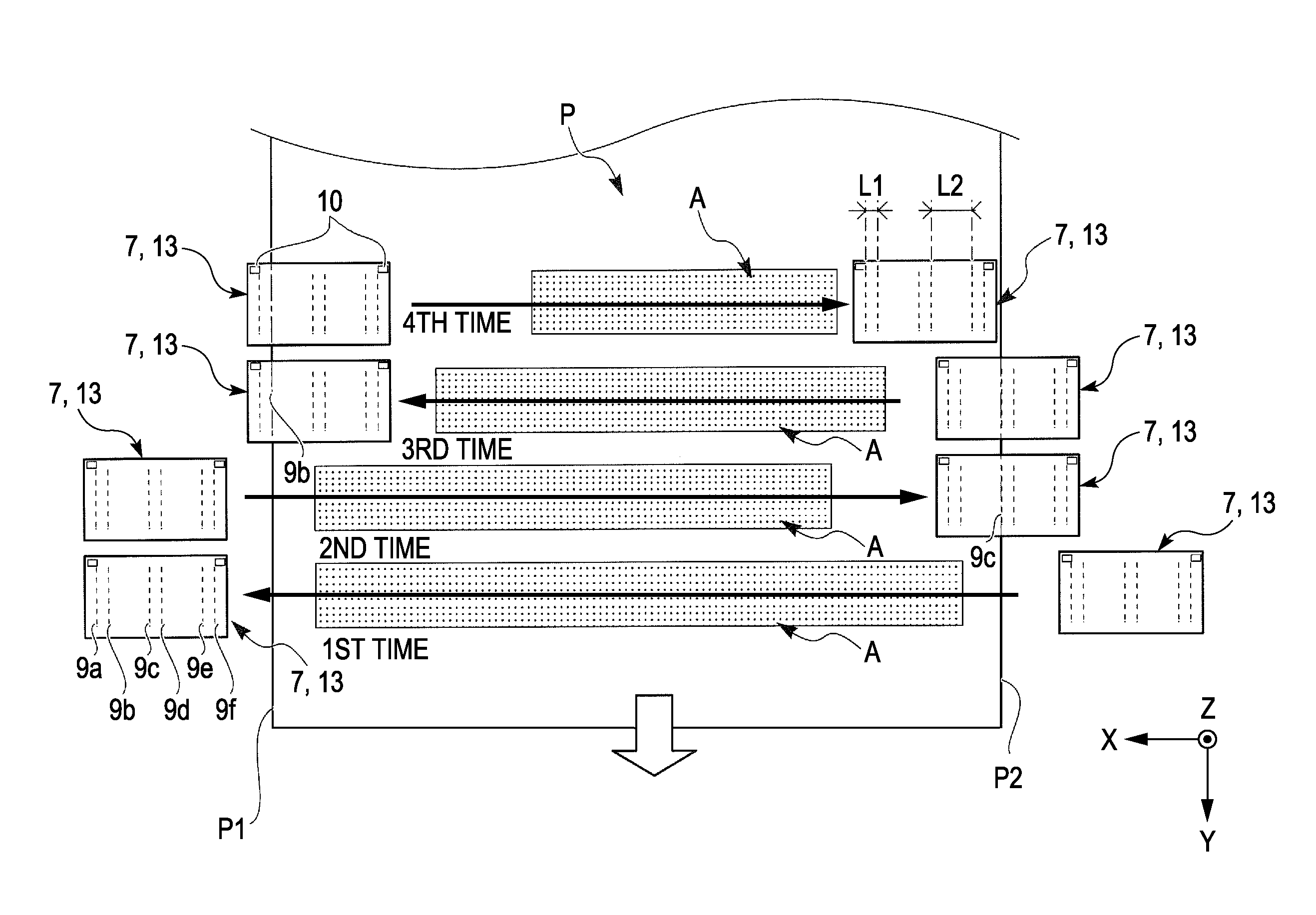
[0051]Hereinafter, an embodiment of the invention will be described on the basis of the drawings.

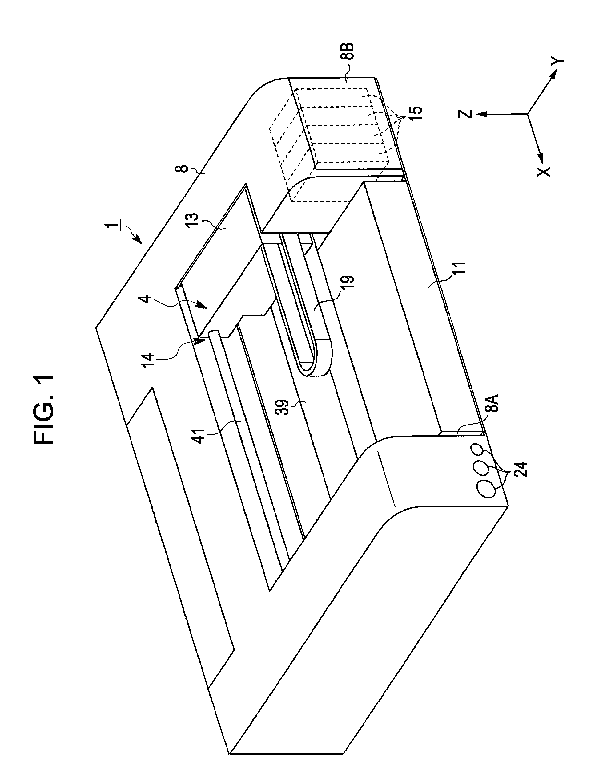
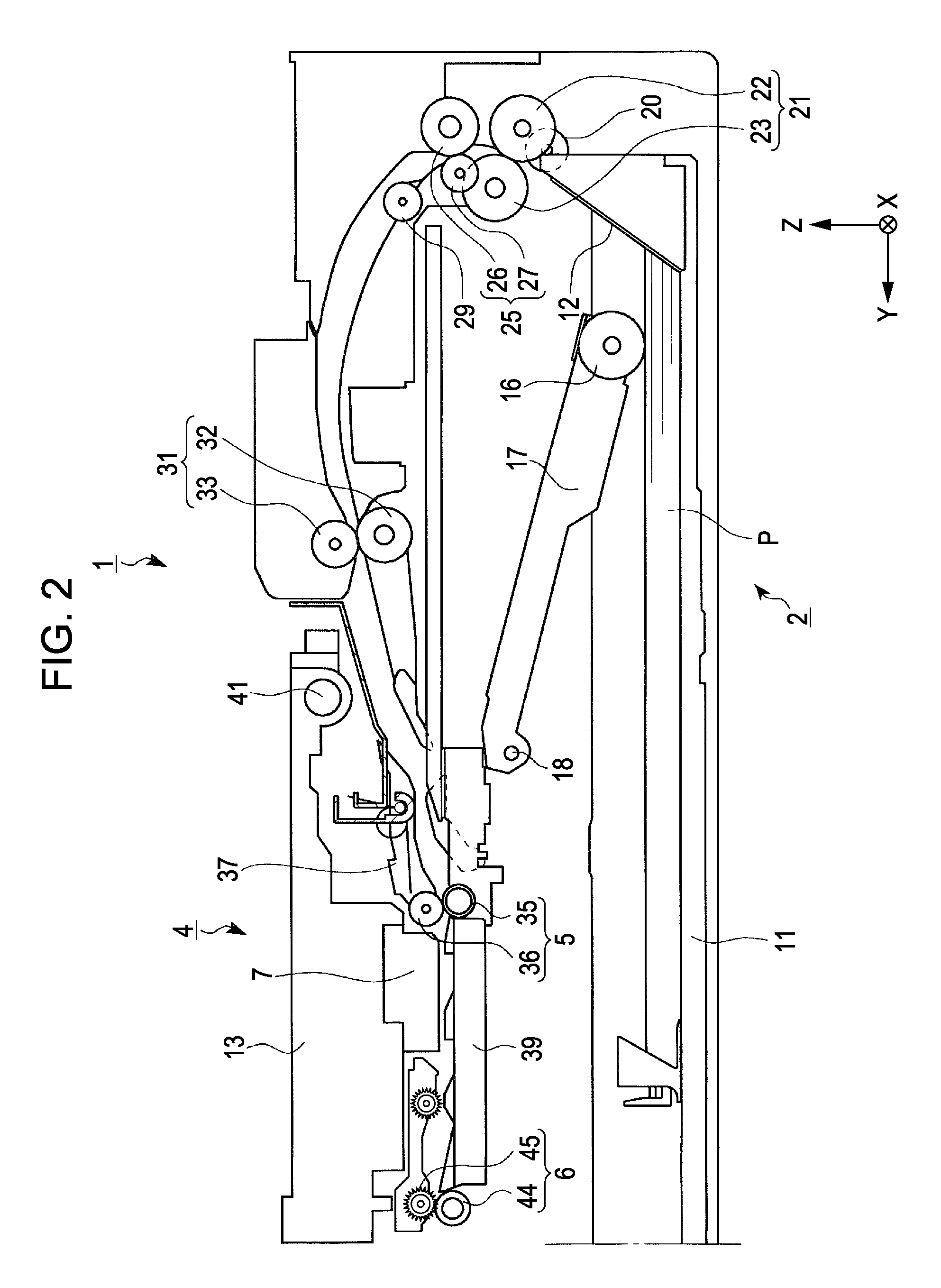
[0052]FIG. 1 shows a perspective view showing a printer as an image forming apparatus related to this embodiment.

[0053]As shown in FIG. 1, a printer 1 is a printer of a form which is thin in a Z-axis direction that is a height direction. Also, the printer 1 has a square box-shaped main body 8. Further, in the central area of the main body 8, a carriage 13 is provided so as to be guided on a carriage guide shaft 41, which is provided so as to extend along a right-and-left direction X (a main scanning direction (the width direction of paper)) in FIG. 1, thereby being capable of reciprocating in the main scanning direction.

[0054]Here, the carriage 13 is set to be configured so as to be moved by a movement section 14. Specifically, the movement section 14 includes a first motor (not shown), a pair of pulleys (not shown), and an endless belt (not shown). The endless belt is wound around the p...


PUM


Abstract

A liquid ejecting apparatus is characterized by a configuration in which it has a first carriage movement mode, in which a stop position of a carriage in movement of this time is determined to be at a given position in a width direction on the basis of a size in the width direction of a liquid-ejected medium, and a second carriage movement mode, in which the stop position of the carriage in the movement of this time is determined on the basis of at least one of the liquid ejection data in this movement and the liquid ejection data in the next movement, and liquid ejection is carried out with one of the first carriage movement mode and the second carriage movement mode selected in accordance with a setting mode that is a mode set up with respect to liquid ejection.

Description

[0001]The entire disclosure of Japanese Patent Application No. 2010-019163, filed Jan. 29, 2010 is expressly incorporated by reference herein.BACKGROUND[0002]1. Technical Field[0003]The present invention relates to a liquid ejecting apparatus which includes a liquid ejecting head having nozzles and ejecting liquid from the nozzles onto a liquid-ejected medium on the basis of liquid ejection data, and a carriage carrying the liquid ejecting head and moving in the width direction of the liquid-ejected medium which is transported, and to a liquid ejecting method in the liquid ejecting apparatus.[0004]In this application, in the liquid ejecting apparatus, recording apparatuses such as ink jet printers, line printers, photocopiers, and facsimiles shall be included. Here, in the line printer, for example, printers shall be included each of which has a configuration in which rows of nozzles are provided to extend in a transportation direction of paper and a carriage having a recording head...

Claims


Application Information

Patent Timeline
Patent Type & Authority Patents(United States)
IPC IPC(8): B41J2/17B41J2/175B41J29/38
CPCB41J29/38B41J29/13B41J2/17509B41J29/02B41J2/2132B41J2/165B41J19/202B41J19/145B41J19/207
Inventor OKI, NARIHIRONAKATA, SATOSHI
Owner SEIKO EPSON CORP
Features
  • R&D
  • Intellectual Property
  • Life Sciences
  • Materials
  • Tech Scout
  • Unparalleled Data Quality
  • Higher Quality Content
  • 60% Fewer Hallucinations
Learn More