Mining automatic high-pressure flushing type camera device and monitoring method thereof

A technology of high-pressure flushing and camera device, which is applied in the cleaning method using gas flow, the cleaning method using liquid, and the method of preventing pollution, etc., which can solve the problems affecting mine monitoring and management, complex working conditions, failure of mechanical joints, etc. , to improve cleanliness and clarity, reduce damage, and extend the length of protection

Active Publication Date: 2020-06-23
HENAN POLYTECHNIC UNIV
View PDF9 Cites 11 Cited by
  • Summary
  • Abstract
  • Description
  • Claims
  • Application Information

AI Technical Summary

Problems solved by technology

However, due to the complex working conditions in the mine, the coal dust and humidity content in the mine air are relatively high
When the camera is used in the mine for a period of time, there will be a layer of attachment on the camera lens, which will directly affect the clarity of the entire full-color camera and affect the monitoring and management of the mine
Therefore, at present, manual cleaning and wiping of the lens is mostly used in mines, but on the one hand, manual cleaning increases the workload and because the camera is placed in a higher position, it makes the cleaning work more difficult. On the other hand, manual cleaning will cause damage to the camera. , reduce the service life of the camera
[0003] In view of the above problems, some scholars try to clean the lens with a cleaning brush, but the cleaning brush head and the rotating rod are mostly mechanically connected, and here often due to dust and other reasons, the mechanical connection fails, and due to the roughness of the attachment Different properties, direct use of the lens brush will cause increased friction on the lens and accelerate damage to the lens

Method used


Image

  • Mining automatic high-pressure flushing type camera device and monitoring method thereof

Examples


Embodiment Construction

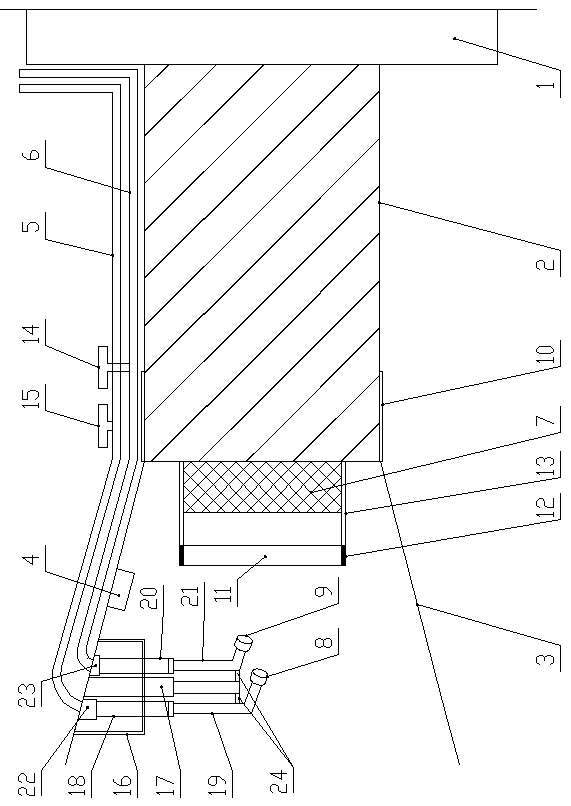
[0020] like figure 1 As shown, the mining automatic high-pressure flushing camera device of the present invention includes a base 1, a camera 2, a conical cover 3, a dust induction identifier 4, a controller, a high-pressure airflow hose 5, a high-pressure water flow hose 6 and a telescopic The nozzle mechanism, the camera 2 is installed on the left side of the base 1, the conical cover 3 is thin on the right and thick on the left, the right end of the conical cover 3 is connected with the left end of the shell of the camera 2, and the camera lens 7 on the left side of the camera 2 is located in the conical cover 3 , the left side of the camera lens 7 is provided with a dust-proof transparent assembly, the dust induction recognizer 4 is arranged inside the cone cover 3 and is used to monitor the dust attached to the left surface of the dust-proof transparent assembly, and the telescopic nozzle mechanism is arranged on the cone cover 3. The top on the left side can be retracted...


PUM


Abstract

The invention discloses a mining automatic high-pressure flushing type camera device. The device comprises a base, a camera, a conical cover, a dust induction recognizer, a controller, a high-pressureairflow hose, a high-pressure water flow hose and a telescopic spray pipe mechanism, a camera lens on the left of the camera is positioned in the conical cover; a dustproof transparent assembly is arranged on the left of the camera lens. The dust induction recognizer is arranged in the conical cover and used for monitoring dust attached to the surface of the left side of the dustproof transparentassembly, the telescopic spray pipe mechanism is arranged at the top of the left side of the conical cover and can stretch out and draw back vertically, and the lower end of the telescopic spray pipemechanism is provided with an airflow sprayer and a water flow sprayer for spraying towards the dustproof transparent assembly. According to the invention, automatic induction is realized through thedust induction recognizer; cleaning is achieved by combining high-pressure water flow, air flow and other pressure intensities, the cleanliness of the dustproof glass can be effectively guaranteed, the high-pressure air flow can effectively achieve the effects of drying and water stain removing, and therefore the workload of manual wiping can be effectively reduced, damage to the camera lens is reduced, and the service life of the camera lens is prolonged.

Description

technical field [0001] The invention belongs to the technical field of mining equipment, and in particular relates to an automatic high-pressure flushing camera device for mining and a monitoring method thereof. Background technique [0002] With the development of intelligent mines, cameras with various functions in mines have been widely used in mines. The use of various high-definition full-color cameras in the mine has improved the overall monitoring and management efficiency. However, due to the complicated working conditions in the mine, the air coal dust and humidity content in the mine are relatively high. When the camera is used for a period of time under the mine, there will be a layer of attachments on the camera lens, which will directly affect the clarity of the entire full-color camera and then affect the monitoring and management of the mine. Therefore, at present, manual cleaning and wiping of the lens is mostly used in mines, but on the one hand, manual cl...

Claims


Application Information

Patent Timeline
Patent Type & Authority Applications(China)
IPC IPC(8): H04N5/225B08B5/02B08B3/02B08B17/02B08B13/00
CPCB08B5/02B08B3/02B08B17/02B08B13/00H04N23/50H04N23/51
Inventor 陈莉罗明南华神文龙
Owner HENAN POLYTECHNIC UNIV
Why Eureka
Try Eureka