Piezoelectric actuator, lens barrel, and camera

a technology of piezoelectric actuators and lens barrels, applied in piezoelectric/electrostriction/magnetostriction machines, instruments, mountings, etc., can solve problems such as complicated control of piezoelectric elements, and achieve the effect of simple control

Active Publication Date: 2014-03-18
NIKON CORP
View PDF2 Cites 0 Cited by
  • Summary
  • Abstract
  • Description
  • Claims
  • Application Information

AI Technical Summary

Benefits of technology

[0007]An object of the aspects of the invention is that it provides a piezoelectric actuator which can be simply controlled and a lens barrel and a camera using the piezoelectric actuator.

Problems solved by technology

Accordingly, there is a problem that a driving circuit is required for the respective piezoelectric elements, and thereby the control of the piezoelectric elements becomes complicating.

Method used


Image

  • Piezoelectric actuator, lens barrel, and camera
  • Piezoelectric actuator, lens barrel, and camera
  • Piezoelectric actuator, lens barrel, and camera

Examples


Embodiment Construction

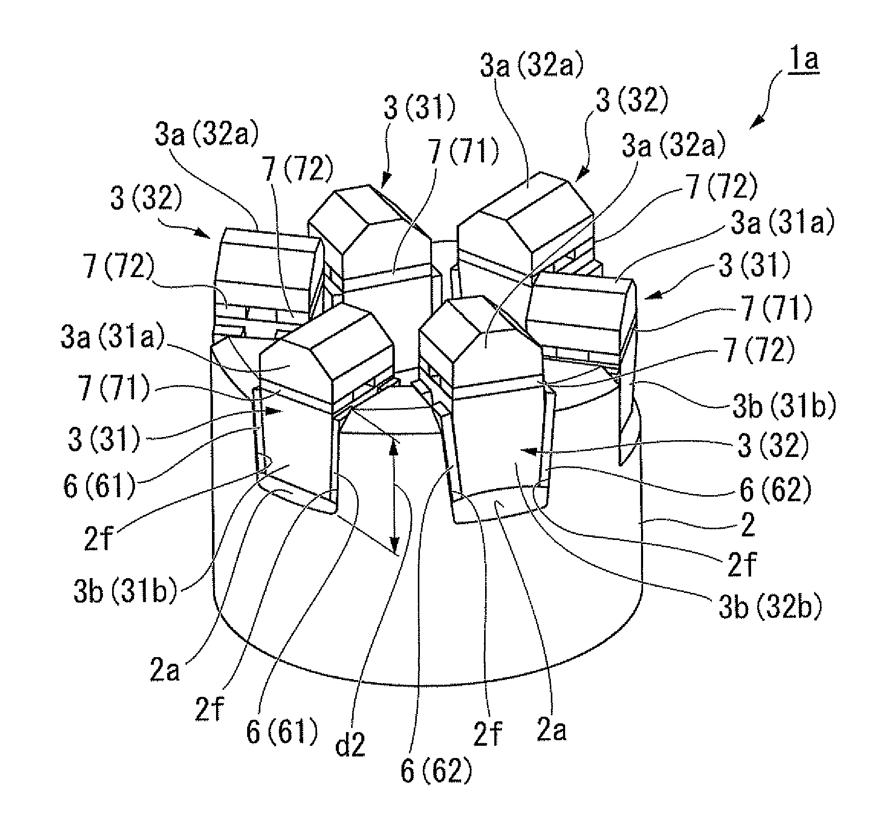
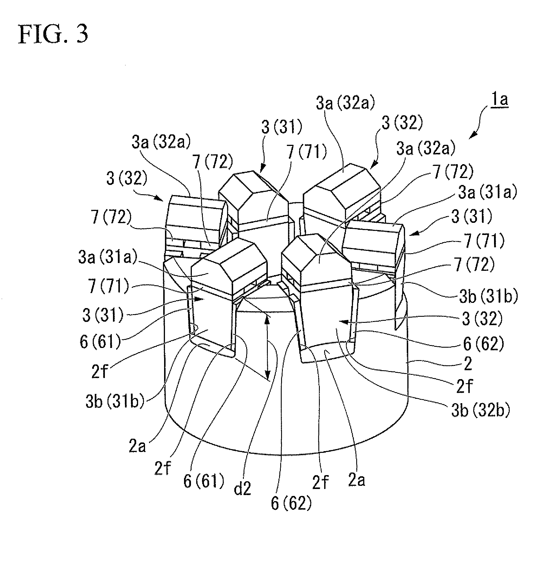
[0032]A piezoelectric actuator according to an embodiment of the invention will be described below with reference to the accompanying drawings. The piezoelectric actuator (driving mechanism) 1 according to this embodiment serves to drive an optical device such as a lens barrel of a camera or an electronic device by, for example, performing a relative driving operation of relatively displacing a member A such as a rotor and a member B such as a driving member.

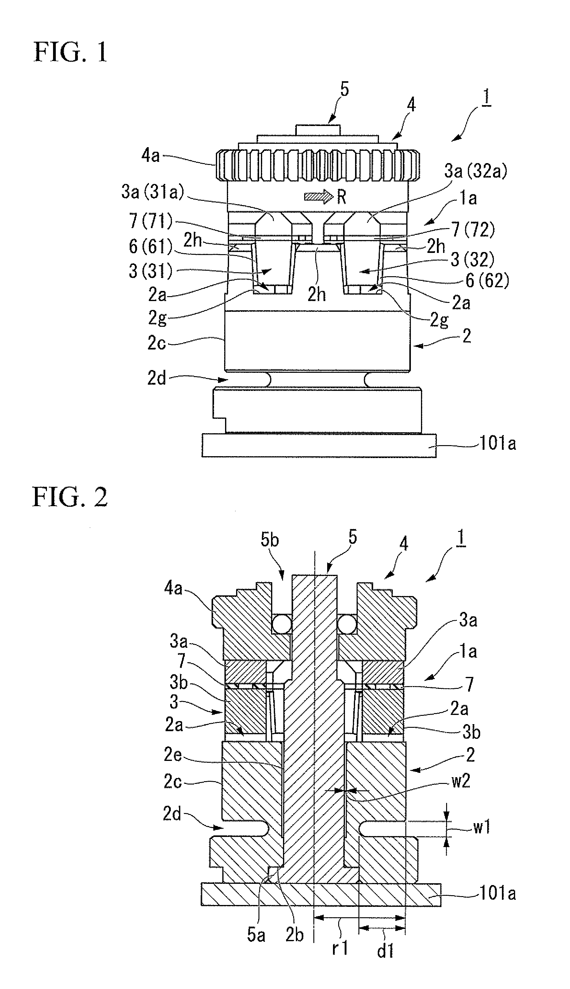
[0033]FIG. 1 is a front view of the piezoelectric actuator 1 according to this embodiment and FIG. 2 is a sectional view thereof.

[0034]As shown in FIGS. 1 and 2, the piezoelectric actuator 1 includes a base member 2 (the fourth member) having a plurality of holding portions 2a, driving members 3 held in the holding portions 2a, a rotor 4 disposed adjacent to the driving members 3, a support shaft 5 inserted through the base member 2, first piezoelectric elements 6, and second piezoelectric elements 7.

[0035]The base member 2 (the...


PUM


Abstract

A piezoelectric actuator comprises a first piezoelectric element, a second piezoelectric element, a first set of a first member that is mounted with the first piezoelectric element which is deformed in a first direction with an application of a first voltage, and a second set of a second member that is mounted with the second piezoelectric element which is deformed in the opposite direction of the first direction with the application of the first voltage.

Description

CROSS-REFERENCE TO RELATED APPLICATION[0001]Priority is claimed on Japanese Patent Application No. 2010-220942, filed on Sep. 30, 2010, the content of which is incorporated herein by reference.BACKGROUND[0002]1. Field of the Invention[0003]The present invention relates to a piezoelectric actuator, a lens barrel, and a camera.[0004]2. Description of Related Art[0005]A piezoelectric actuator (a driving apparatus) using a piezoelectric element is known in which a driving target member is driven by driving a plurality of piezoelectric elements and the tip members which is in contact with the driving target member elliptically. For example, the piezoelectric actuator described in JP-A-2007-236138, drives the driving target member in the X axis direction by the elliptical movement parallel to the XZ plane of the tip members when an XYZ orthogonal coordinate system is provided.SUMMARY[0006]However, the piezoelectric actuator is controlled by controlling the frequencies and the phases of vo...

Claims


Application Information

Patent Timeline
Patent Type & Authority Patents(United States)
IPC IPC(8): G02B7/02
CPCG02B7/04H02N2/101G02B7/08H02N2/021
Inventor KUWANO, KUNIHIROKIMURA, MASAMITSU
Owner NIKON CORP
Why Eureka
Try Eureka