Copper electroplating bath

a copper electroplating and copper bath technology, applied in the direction of coating, printed circuit manufacturing, printed element electric connection formation, etc., can solve the problems of voids, voids, and worsening the current distribution inside the via hole, so as to achieve simple control of conformity

Active Publication Date: 2014-03-25
C UYEMURA & CO LTD
View PDF33 Cites 3 Cited by
  • Summary
  • Abstract
  • Description
  • Claims
  • Application Information

AI Technical Summary

Benefits of technology

[0035]According to the invention, the capability of fill plating with copper of an electrolytic copper plating bath for filling blind via holes formed on a substrate with plated copper can be simply controlled in conformity with the size of the blind via holes only by changing a quaternary nitrogen to tertiary nitrogen ratio of a water-soluble polymer serving as a leveler, thereby permitting electrolytic copper plating to be performed in conformity with different sizes of blind via holes.

Problems solved by technology

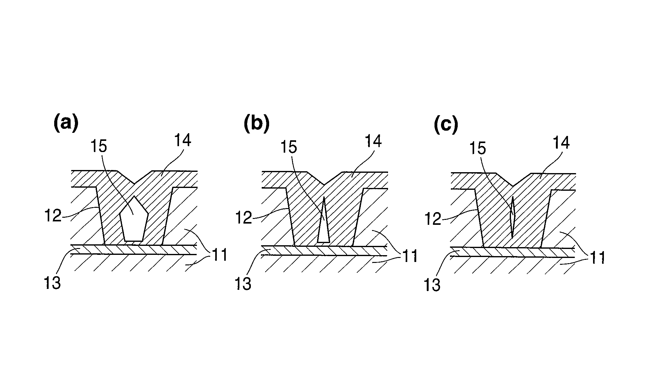
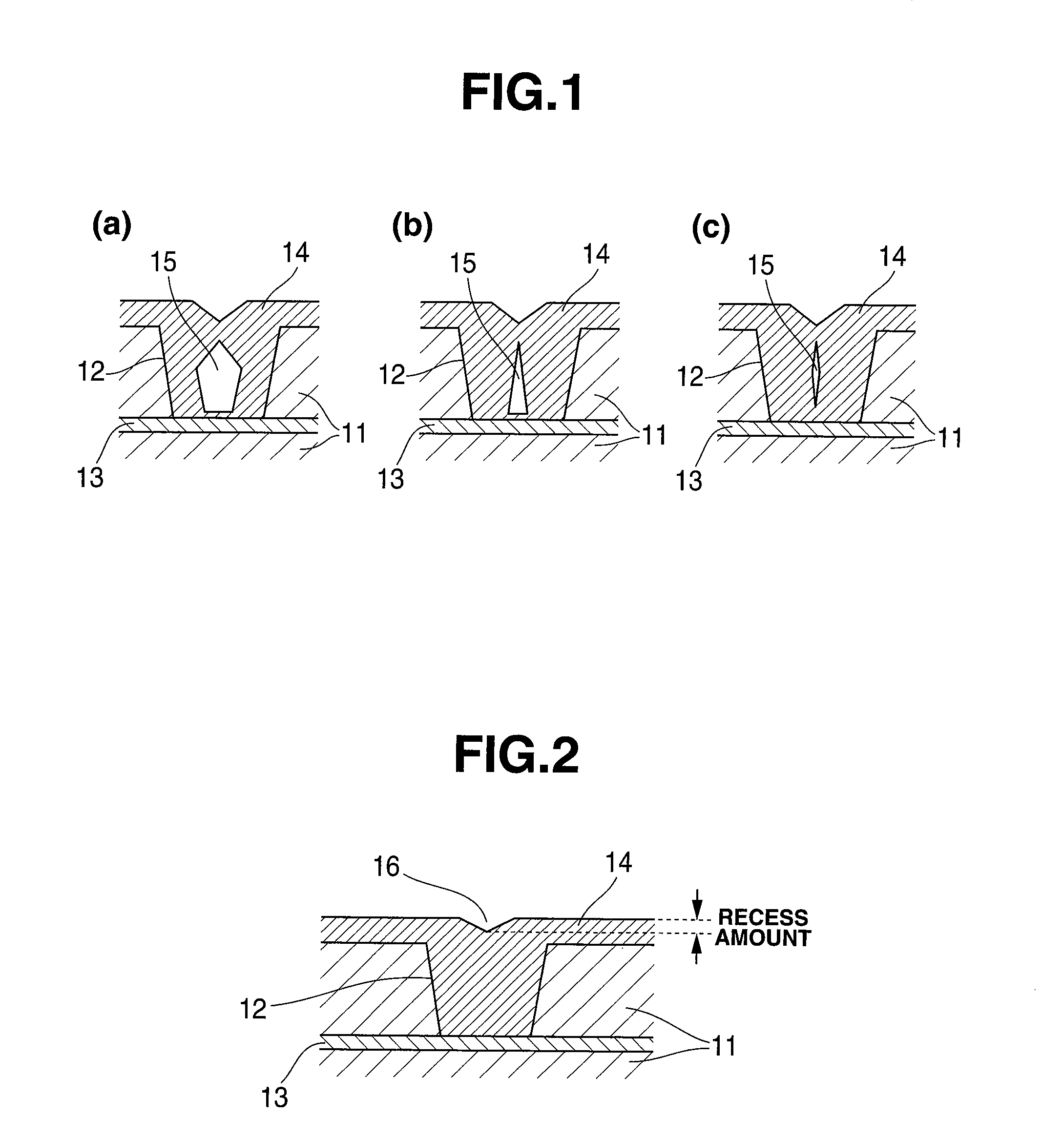
Where via holes having a small diameter or deep via holes are filled with plated copper according to such a technique, a difference in potential between the surface side and the bottom of the via hole substrate becomes great thereby worsening a current distribution inside the via holes.
Accordingly, if no effects of the additives are expected, deposition in the vicinity of the surface becomes larger than at the bottom to cause voids to occur.
Thus, filling with plated copper is not possible.
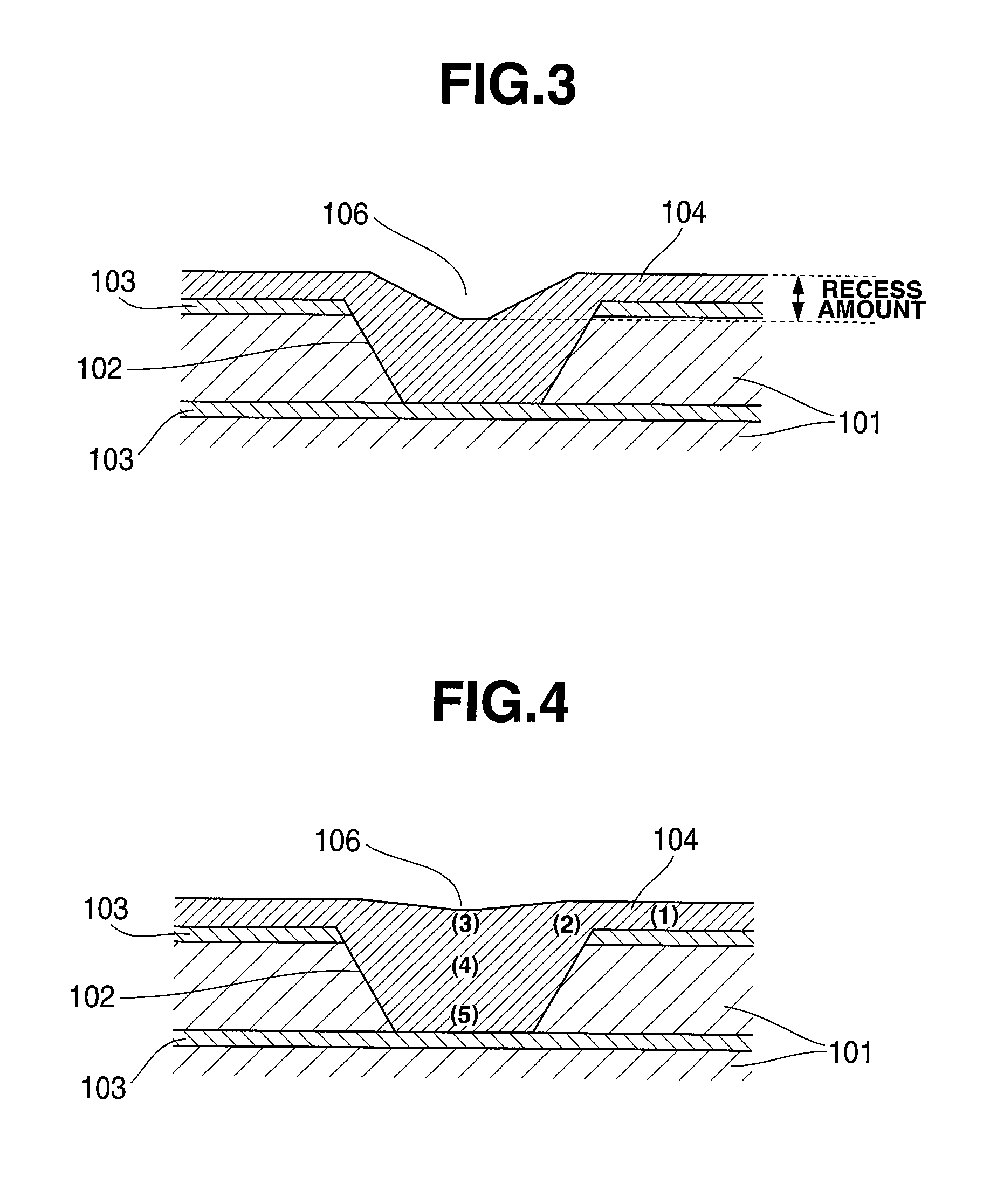
In addition, with respect to the difference in concentration gradient caused by diffusion in the plating bath, i.e. the thickness of the diffusion layer, where the via hole has a small diameter or depth, the difference between the vicinity of the surface and the bottom of the via hole becomes great, resulting in a thick via bottom.

Method used


Image

  • Copper electroplating bath
  • Copper electroplating bath
  • Copper electroplating bath

Examples


examples

[0084]The present invention is more particularly illustrated by way of Examples, which should not be construed as limiting the invention thereto.

examples 1 to 8

[0085]Electrolytic copper plating baths indicated in Table 1 were used for carrying out the following plating operations to evaluate plating characteristics.

[0086]

TABLE 1Copper sulfateAdditives (mg / L)pentahydrateSulfuric acidChlorineBrightenerCarrierLeveler(g / L)(g / L)(mg / L)SPSPEGPPGPO-EOABCDEFKindNitrogenExample1200505013005AQuaternary22005050130023A + CTertiary +Quaternary(mix)3200505013005BTertiary +Quaternary4200505013005CTertiary5200505013005DQuaternary620050501300222D + E + FTertiary +Quaternary(mix)7200505013005ETertiary +Quaternary8200505013005FTertiarySPS: bis-(3-sodium sulfopropyl)disulfidePEG: polyethylene glycol (molecular weight of 7500)PPG: polypropylene glycol (molecular weight of 900)PO-EO: propylene glycol-ethylene glycol block copolymer (molecular weight of 1500)Leveler A: poly(N-vinyl-N′-methylimidazolium chloride)Leveler B: copolymer of vinylpyrrolidone and vinylimidazolium quaternized productLeveler C: poly(N-vinylpyrrolidone)Leveler D: poly(diallyldimethylammoniu...


PUM

PropertyMeasurementUnit
hole diameteraaaaaaaaaa
aspect ratioaaaaaaaaaa
hole diameteraaaaaaaaaa

Abstract

A copper electroplating bath useful in filling non-through holes formed on a substrate which contains a water-soluble copper salt, sulfuric acid, and chloride ions and further contains a brightener, a carrier, and a leveler as additives, wherein the leveler contains at least one water-soluble polymer containing quaternary nitrogen, tertiary nitrogen, or both which are cationizable in a solution. In the copper electroplating bath, the filling power for non-through holes formed on a substrate can be easily controlled so as to fit to the size of the holes only by changing the quaternary nitrogen to tertiary nitrogen ratio of the water-soluble polymer to be used as the leveler, which enables copper electroplating of non-through holes of various sizes with a good fit to the sizes.

Description

TECHNICAL FIELD[0001]The present invention relates to an electrolytic copper plating bath wherein the capability of filling, with copper by plating, blind via holes formed on a substrate can be optimized in conformity with the size of the blind via holes.BACKGROUND ART[0002]As miniaturization of electronic parts is in progress and a higher degree of integration has been therefore demanded, packages are transferred from peripheral terminal packaging and area terminal packaging to three-dimensional packaging. Accordingly, with semiconductor chips and interposers, electric conduction or junction with TSV (through silicon via) has been under study for putting into practical use. For the TSV (through silicon via), it is required to fill via holes with a copper plated film by electrolytic copper plating like copper damascene or via filling of printed circuit boards. In printed circuit boards, it becomes necessary to simultaneously carry out via filling and through-hole plating.[0003]The c...

Claims


Application Information

Patent Timeline
Patent Type & Authority Patents(United States)
IPC IPC(8): C25D3/38H05K3/42H01L21/02C25D3/00C25D3/02
CPCC25D3/02H01L21/76877H05K3/424H01L21/2885H01L21/02C25D3/00H05K3/423H01L21/76898C25D3/38
Inventor ISONO, TOSHIHISATACHIBANA, SHINJIKAWASE, TOMOHIROOMURA, NAOYUKI
Owner C UYEMURA & CO LTD
Why Eureka
Try Eureka