Method for checking the integrity of composite load bearing member

a composite member and integrity technology, applied in the field of inspection of the integrity of the composite load bearing member, can solve the problems of prone to different kinds of defects, voids, porosity, inclusions, etc., and achieve the effect of facilitating the ability of the load bearing to achieve high tensile stiffness

Pending Publication Date: 2019-07-18
KONE CORP
View PDF22 Cites 2 Cited by
  • Summary
  • Abstract
  • Description
  • Claims
  • Application Information

AI Technical Summary

Benefits of technology

[0030]In a preferred embodiment, the reinforcing fibers are distributed substantially evenly in the polymer matrix. They are bound to each other by the polymer matrix. Furthermore, preferably, over 50% of the cross-sectional square area of the composite member consists of said reinforcing fibers. Thereby, load bearing ability with high tensile stiffness can be facilitated. The reinforcing fibers f are preferably long continuous fibers in the longitudinal direction of the elongated composite member, preferably continuing unbroken throughout the whole length of the elongated composite member. Preferably, substantially all the reinforcing fibers f of each composite member are parallel with the longitudinal direction of the composite member. The composite member formed is a solid elongated rod-like one-piece structure.
[0031]In a preferred embodiment, the composite member is inspected either naked of additional rope components, such as other composite members or substantial amount of coating, or while it has additional rope components attached thereto, said additional rope components including one or more composite members and / or a coating. In the latter case, the composite member is comprised in a rope and embedded in a coating forming the outer surface of the rope and said scanning is performed through the coating. The coating is preferably made of polymer material. Presence of the coating on the composite member may be in some cases advantageous as in this way defects in the coating can also detected. Then, the method is used also to inspect quality and / or condition of the coating. This may be advantageous particularly when the coating has a complicated contoured structure, such as grooved structure.

Problems solved by technology

Therefore, they are also prone to different kind of defects, caused already in manufacturing or degradation in use.
Beside delamination and cracks, other examples of significant flaws in composites are: voids, porosity, inclusions, wear, impact damage, incorrect cure and fibre breakage, wrinkling or waviness.
Many of the flaws and failures occur first without being detrimental for the integrity of the structure.
Accumulation of structural failures under load results leads in a progressively increasing number of detectable failures before final catastrophic failure.
It has been now found out that prior art inspection methods, such as those monitoring electric properties, do not reliably reveal all kinds of defects in fiber-composite members.

Method used


Image

  • Method for checking the integrity of composite load bearing member
  • Method for checking the integrity of composite load bearing member
  • Method for checking the integrity of composite load bearing member

Examples


first embodiment

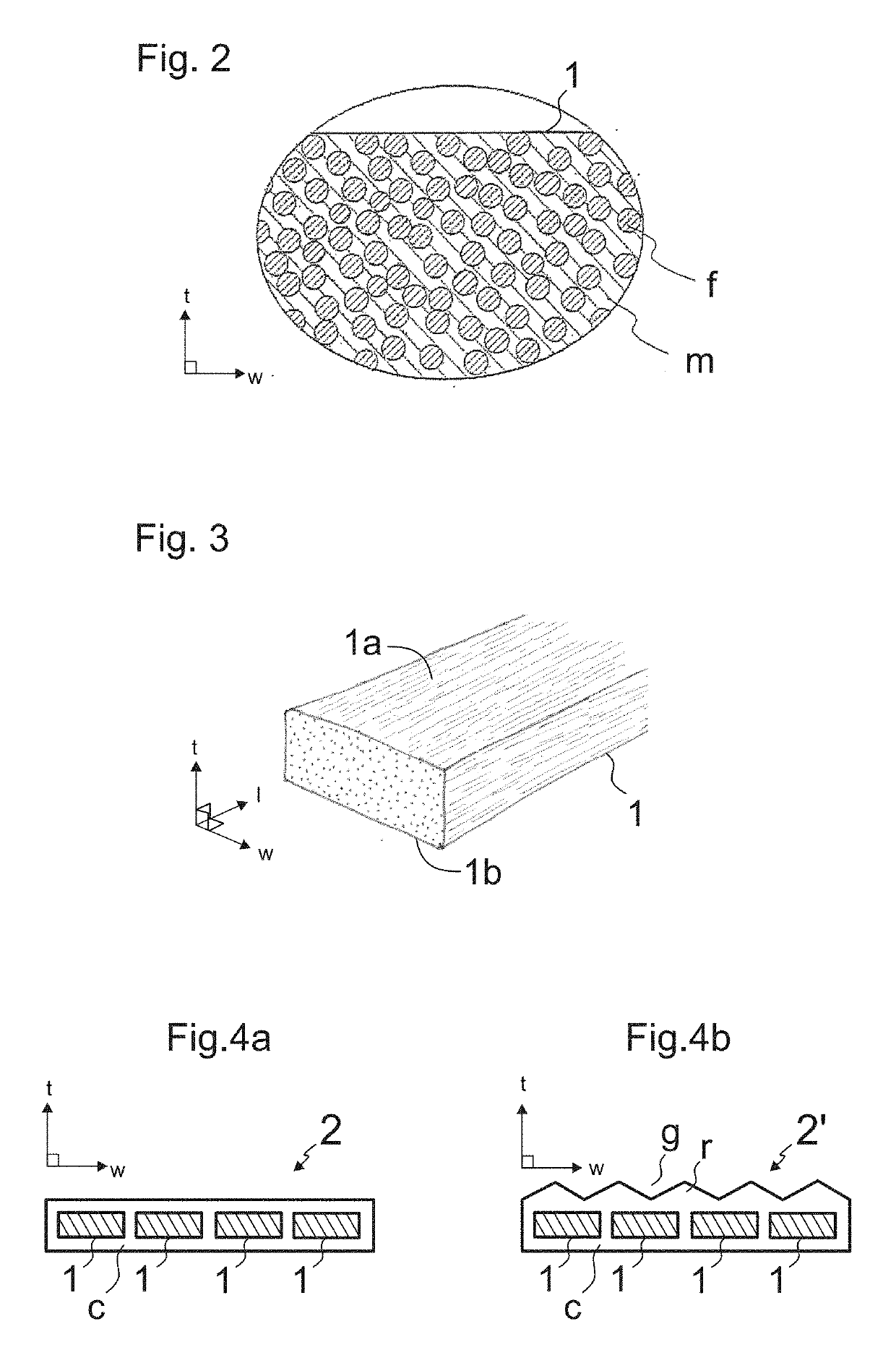
[0068]FIG. 9 illustrates a first preferred embodiment of the method. In this embodiment, the method is performed during the manufacturing of a rope, such as a rope 2,2′ illustrated in FIG. 4a or 4b. The inspection can be carried out basically in any point of a manufacturing line of the rope 2,2′ after formation of the composite member 1. The elongated composite member may or may not have a coating c. The elongated composite member 1 to be inspected is guided to run via a stationary inspection station A,B,C comprising said thermal imaging device 3. Said elongated composite member 1 passes past said thermal imaging device 3, which continuously or intermittently performs scanning of said elongated composite member 1. The whole length of the composite member 1 can be guided to run via a stationary inspection station A,B,C comprising said thermal imaging device 3 so the whole length thereof can be inspected. The method can this way be performed as an on-line inspection method in a factor...

second embodiment

[0077]FIG. 12 illustrates a second preferred embodiment of the method. In this embodiment, the method is performed during the manufacturing of a rope, such as a rope 2,2′ illustrated in FIG. 4a or 4b. The inspection can be carried out basically in any point of a manufacturing line of the rope 2,2′ after formation of the elongated composite member 1. The elongated composite member may or may not have a coating c. The elongated composite member 1 to be inspected is guided to run via a stationary inspection station D, E, F, G, H, I comprising said thermal imaging device 3. Said elongated composite member 1 passes past said thermal imaging device 3, which continuously or intermittently performs scanning of said elongated composite member 1. The whole length of the composite member 1 can be guided to run via a stationary inspection station D, E, F, G, H, I comprising said thermal imaging device 3 so the whole length thereof can be inspected. The method can this way be performed as an on-...


PUM

PropertyMeasurementUnit
temperatureaaaaaaaaaa
thermal imagingaaaaaaaaaa

Abstract

The invention relates to a method for inspecting quality and/or condition of an elongated composite member, which is a load bearing member of a rope of a hoisting apparatus, such as an elevator, or a precursor of such a load bearing member, the method comprising providing an elongated composite member; and changing the temperature of said elongated composite member by heating or cooling said elongated composite member via a flank thereof; and scanning said elongated composite member from a lateral side thereof with a thermal imaging device after said changing of the temperature; and creating thermographic images of said elongated composite member.

Description

[0001]This application is a continuation of PCT International Application No. PCT / EP2017 / 077888 which has an International filing date of Oct. 31, 2017, which claims priority to European Application No. 16196570.2, filed on Oct. 31, 2016, the entire contents of each of which are incorporated herein by reference.FIELD OF THE INVENTION[0002]The invention relates to inspecting condition of an elongated composite member of a rope of a hoisting apparatus. The hoisting apparatus is preferably an elevator for vertically transporting passengers and / or goods.BACKGROUND OF THE INVENTION[0003]In hoisting devices such as elevators, one or more ropes are used as the means by which the load to be hoisted is suspended. Each elevator rope typically includes one or more load bearing members that are elongated in the longitudinal direction of the rope, each forming a structure that continues unbroken throughout the length of the rope. Load bearing members are the members of the rope which are able to...

Claims


Application Information

Patent Timeline
Patent Type & Authority Applications(United States)
IPC IPC(8): G01N25/72B29C70/52B29C48/154
CPCG01N25/72B29C70/528B29C48/154B66B7/1215B29L2031/707
Inventor ANTIN, KIMBOSSUYT, SVENHASSINEN, ANTTIHELENIUS, JUHAHONKANEN, JUHAJUNTUNEN, MIKAKERE, PETRILASSILA, MIKKOLEHTINEN, HANNUNAREIKKO, ALEKSIPURANEN, MIKKORUOTSALAINEN, KAIVALJUS, PETTERI
Owner KONE CORP
Why Eureka
Try Eureka