Method and system for providing a read transducer having a reduced shield-to-shield spacing

a technology of shield-to-shield spacing and read transducer, which is applied in the field of providing a read transducer having a reduced shield-to-shield spacing, can solve the problems of undesirable instabilities in the magnetoresistive sensor b>20/b>, adversely affecting the thermal stability of the magnetoresistive sensor, and saf structure may be vulnerable to reversal

Active Publication Date: 2014-03-18
WESTERN DIGITAL TECH INC
View PDF116 Cites 182 Cited by
  • Summary
  • Abstract
  • Description
  • Claims
  • Application Information

AI Technical Summary

Benefits of technology

[0006]FIG. 1 depicts an ABS view of a co...

Problems solved by technology

However, such reductions in the thickness of the AFM layer 22 adversely affect the thermal stability of the magnetoresistive sensor 20.
Such instabilities in the m...

Method used


Image

  • Method and system for providing a read transducer having a reduced shield-to-shield spacing
  • Method and system for providing a read transducer having a reduced shield-to-shield spacing
  • Method and system for providing a read transducer having a reduced shield-to-shield spacing

Examples


Embodiment Construction

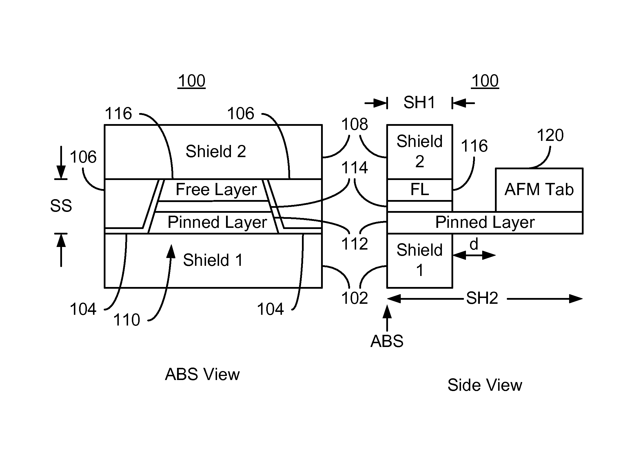
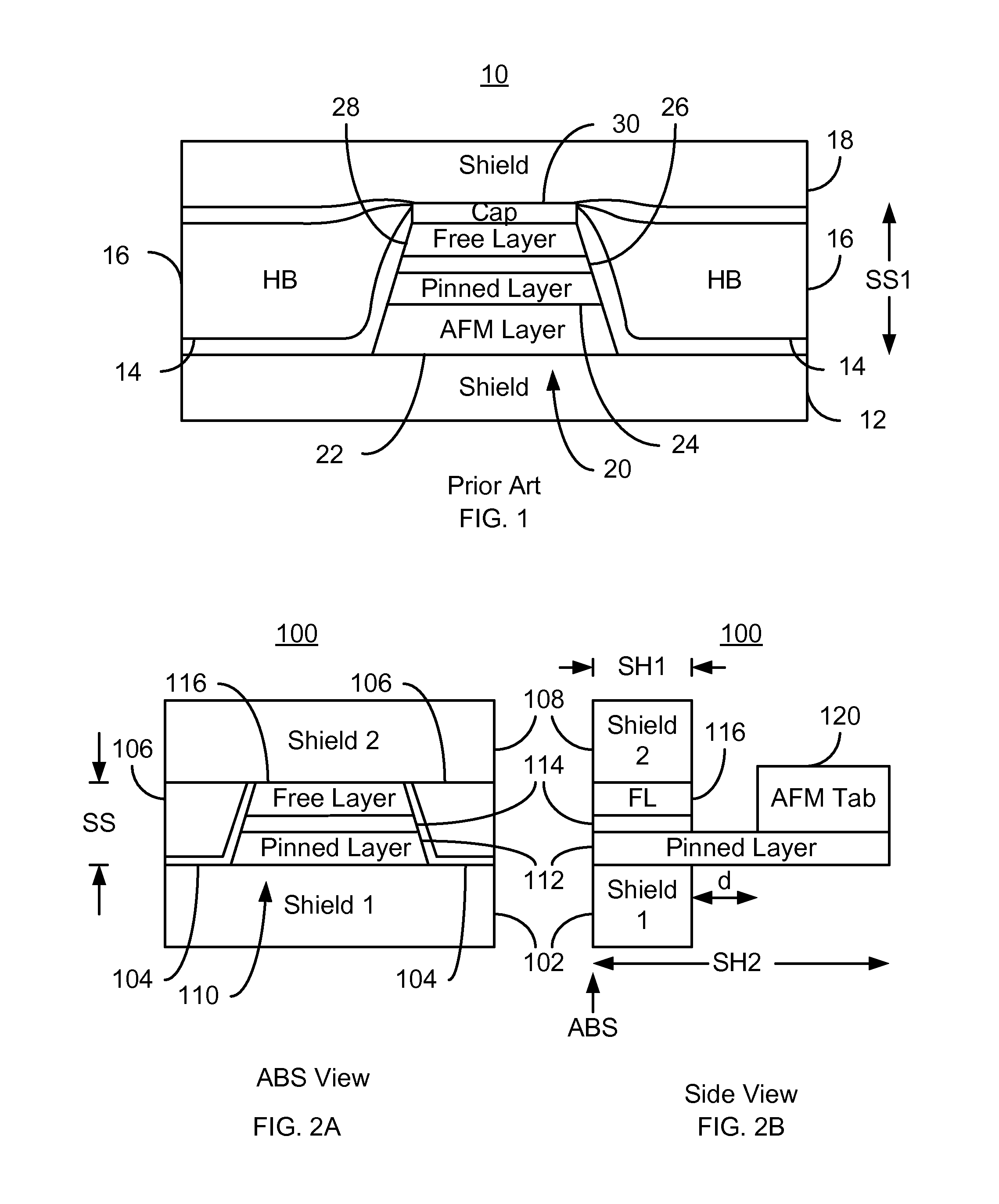
[0021]FIGS. 2A-2B depict ABS and side views of an exemplary embodiment of a portion of a magnetic read transducer 100. For clarity, FIGS. 2A-2B are not to scale. The read transducer 100 may be part of a read head or may be part of a merged head that also includes a write transducer. The head of which the read transducer 100 is a part is part of a disk drive having a media, a slider and the head coupled with the slider. Further, only a portion of the components of the read transducer 100 are depicted.

[0022]The transducer 100 includes soft magnetic shields 102 and 108, insulator 104, biasing layers 106, and a read sensor 110. The sensor 110 includes a pinned layer 112, a nonmagnetic spacer layer 114, and a free layer 116. The pinned layer 112 and free layer 116 are ferromagnetic. However, the magnetization of the pinned layer 112 is stable, while that of the free layer 116 may respond to an external magnetic field. The pinned layer 112 is shown as a single layer. However, in some embo...


PUM


Abstract

A method and system for providing a read magnetic transducer having an air-bearing surface (ABS) is described. The magnetic read transducer includes a first shield, a read sensor stack, an antiferromagnetic (AFM) tab, and a second shield. The read sensor stack includes a pinned layer, a spacer layer, and a free layer. The spacer layer is nonmagnetic and between the pinned layer and the free layer. A portion of the read sensor stack is at the ABS. The AFM tab is recessed from the ABS and adjacent to a portion of the pinned layer. The read sensor resides between the first shield and the second shield.

Description

BACKGROUND[0001]FIG. 1 depicts an air-bearing surface (ABS) view of a conventional read transducer used in magnetic recording technology applications. The conventional read transducer 10 includes shields 12 and 18, insulator 14, hard bias structures 16, and sensor 20. The read sensor 20 is typically a giant magnetoresistive (GMR) sensor or tunneling magnetoresistive (TMR) sensor. The read sensor 20 includes an antiferromagnetic (AFM) layer 22, a pinned layer 24, a nonmagnetic spacer layer 26, and a free layer 28. Also shown is a capping layer 30. In addition, seed layer(s) may be used. The free layer 28 has a magnetization sensitive to an external magnetic field. Thus, the free layer 28 functions as a sensor layer for the magnetoresistive sensor 20. If the sensor 20 is to be used in a current perpendicular to plane (CPP) configuration, then current is driven in a direction substantially perpendicular to the plane of the layers 22, 24, 26, and 28. Conversely, in a current parallel to...

Claims


Application Information

Patent Timeline
IPC IPC(8): G11B5/39
CPCG11B5/398G11B5/3912G11B5/39
Inventor HO, KUOK SANGIDER, SAVASMAURI, DANIELEMAO, MINGMAO, SINING
Owner WESTERN DIGITAL TECH INC
Why Eureka
Try Eureka