Ribbon microphone with automatic protection switch

a microphone and automatic protection technology, applied in the field of microphones, can solve the problems of affecting the performance of the microphone, affecting the performance of the deaf-aid set, and the extension of the state, and achieve the effect of reducing impedance and improving versatility

Inactive Publication Date: 2014-03-18
AUDIO-TECHNICA
View PDF1 Cites 4 Cited by
  • Summary
  • Abstract
  • Description
  • Claims
  • Application Information

AI Technical Summary

Benefits of technology

[0017]According to the invention, in a ribbon microphone operable with a phantom power supply, a switch (preferably a normally closed photorelay including a light emitting diode that emits light by a power supplied from a phantom power supply) is connected across the secondary winding of a step-up transformer, and the switch is normally closed and is opened by a power supplied from the phantom power supply. In this way, when the phantom power supply is not connected and the microphone is not in use, the switch is closed (i.e. turned on) to leave the secondary winding side in a short-circuited state, which extremely reduces impedance on the primary winding side according to the impedance ratio of the step-up transformer (1:N2, where N is the number of turns on the secondary side) to create a closed circuit including the diaphragm. This provides electromagnetic damping on the diaphragm. On the other hand, when the phantom power supply is connected for supplying a power (and the microphone is in use), the switch turns off (i.e. opened), which releases the electromagnetic damping on the diaphragm. The invention, therefore, eliminates the need for a special connector incorporating a mechanical switch as set forth in Japanese Patent Application Publication No. 2009-218685, thereby improving versatility.

Problems solved by technology

A problem with a ribbon microphone is that, on impact against the microphone, an inertial force of the diaphragm (sometimes referred to as “ribbon”) 10 stretches the ribbon foil, leaving it in an elongated state by plastic deformation.
When a ribbon plastic-deformed in this way contacts a magnetic pole or a nearby component, the performance may significantly be degraded.
Besides shocks during transportation, however, other shocks on impact against a microphone include a drop impact experienced, for example, when the microphone is accidentally dropped while being handled on a microphone stand for attachment.

Method used


Image

  • Ribbon microphone with automatic protection switch
  • Ribbon microphone with automatic protection switch
  • Ribbon microphone with automatic protection switch

Examples


Embodiment Construction

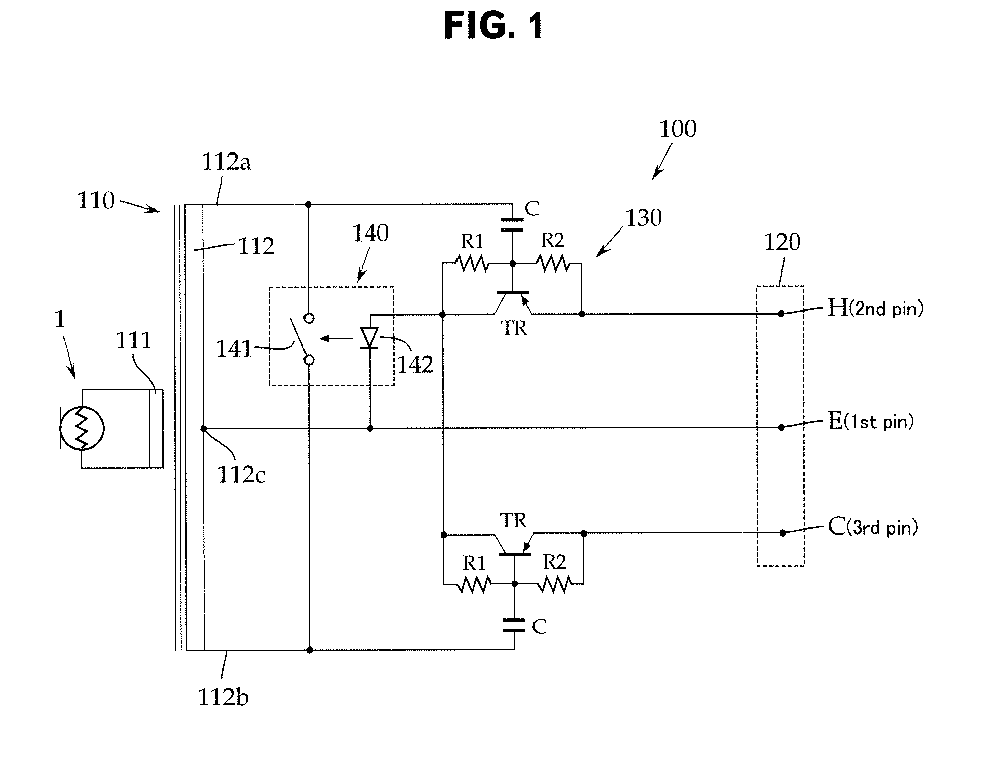
[0020]An embodiment of the invention will now be described with reference to FIG. 1, although the present invention is not limited to the embodiment.

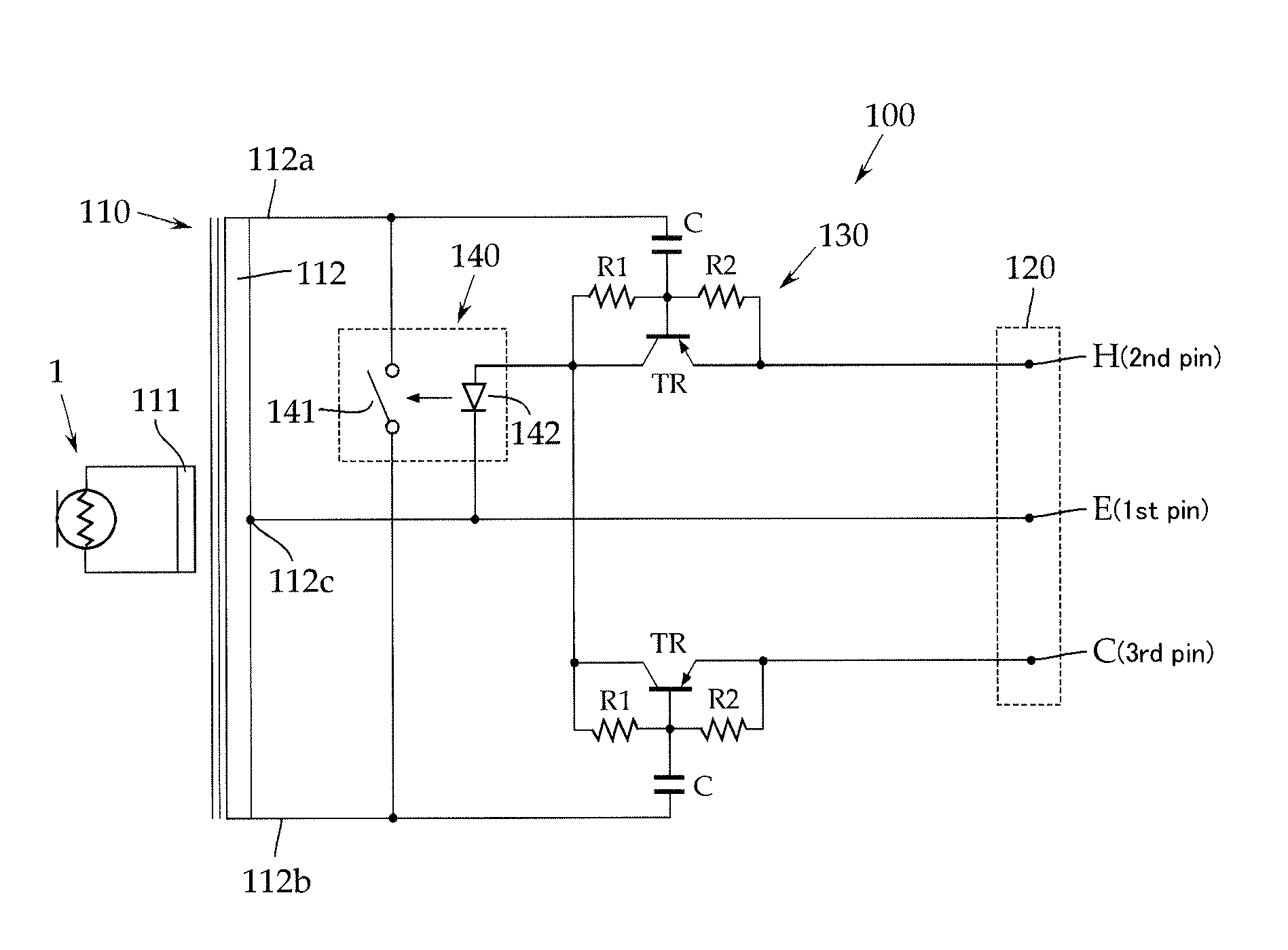
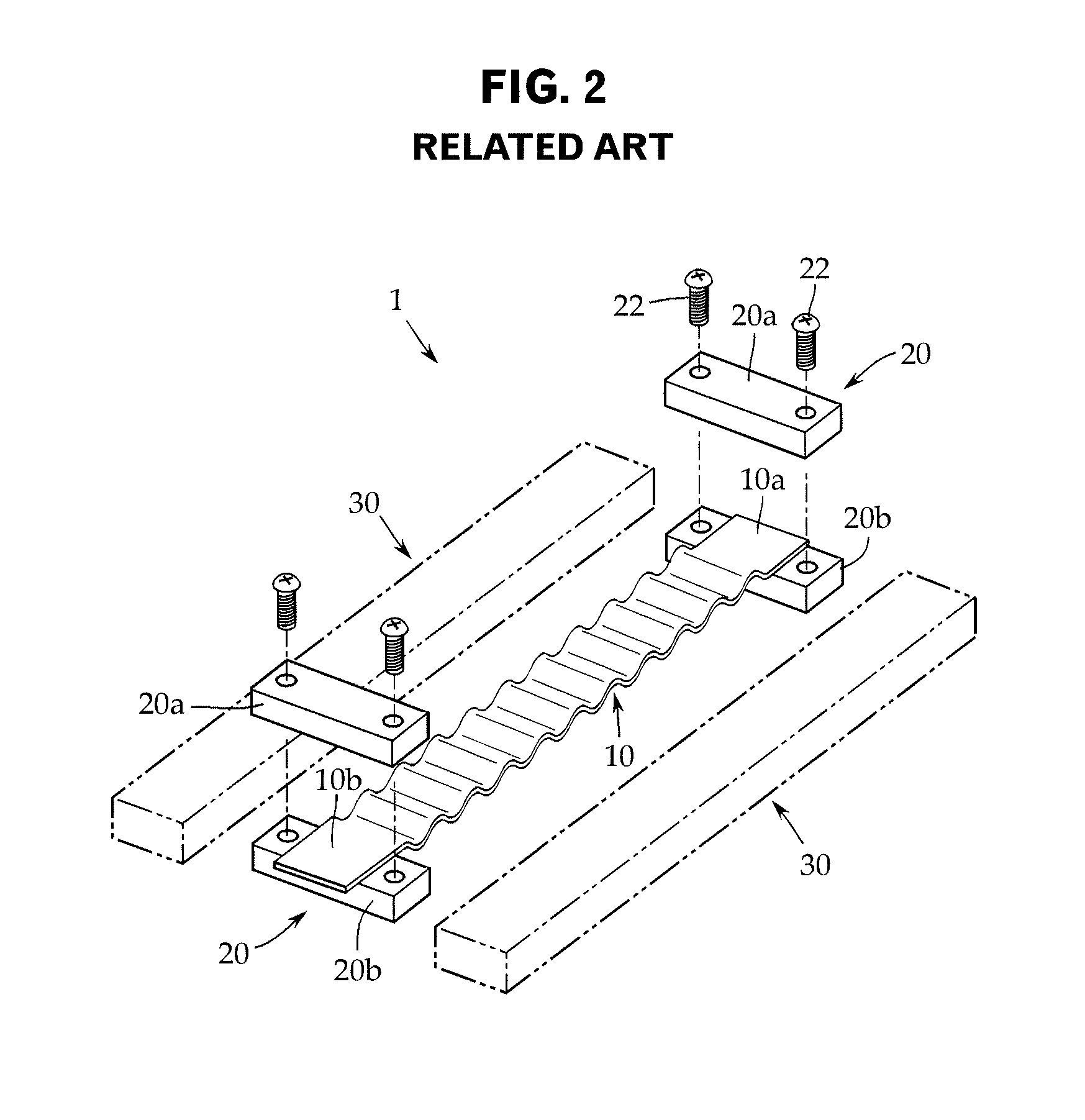
[0021]As shown in FIG. 1, a ribbon microphone 100 according to the embodiment is provided with an acoustic-electric converter (i.e. microphone unit) 1 having a ribbon foil used as a diaphragm. With reference to FIG. 2 again, the acoustic-electric converter 1 may have a metallic foil such as an aluminum foil in the form of a strip of several micrometers thick as a diaphragm 10. The foil is placed in a parallel magnetic field formed by a pair of permanent magnets 30 facing each other with a predetermined space therebetween.

[0022]Since the ribbon microphone 100 is operable with a phantom power supply (not shown), the ribbon microphone 100 is provided with a step-up transformer 110 and an output connector 120 that is to be connected to the phantom power supply.

[0023]Attachment electrodes 20 attached to opposite ends of the diaphragm 10 (see...


PUM


Abstract

To provide electromagnetic damping without a special output connector for protecting a diaphragm of metallic ribbon foil of a ribbon microphone against shocks. A ribbon microphone operable with a phantom power supply comprises: an acoustic-electric converter 1 including a pair of permanent magnets and a diaphragm of metallic ribbon foil; and a step-up transformer 110 coupled with the diaphragm on a primary winding 111 side and having, on a secondary winding 112 side, an output connector 120 removably connected to a phantom power supply, the step-up transformer 110 increasing a voltage generated by the diaphragm to a predetermined voltage, the voltage then being output to the phantom power supply side through the output connector 120, wherein a switch 141 is connected across the secondary winding 112, the switch 141 being normally closed and being opened by a power supplied from the phantom power supply.

Description

CROSS-REFERENCE TO RELATED APPLICATION[0001]The present application is based on, and claims priority from, Japanese Application Serial Number JP2011-009574, filed Jan. 20, 2011, the disclosure of which is hereby incorporated by reference herein in its entirety.TECHNICAL FIELD[0002]The present invention relates to a ribbon microphone having a metallic ribbon foil used as a diaphragm, and in particular to a technique for protecting the diaphragm against shocks or the like.BACKGROUND ART[0003]As shown in FIG. 2, such a ribbon microphone is provided with an acoustic-electric converter (i.e. microphone unit) 1. The converter 1 has a metallic foil such as an aluminum foil in the form of a strip of several micrometers thick as a diaphragm 10. The foil is placed in a parallel magnetic field formed by a pair of permanent magnets 30 facing each other with a predetermined space therebetween. Attachment electrodes 20, which include a pair of support electrode plates 20a and 20b, are attached to...

Claims


Application Information

Patent Timeline
Patent Type & Authority Patents(United States)
IPC IPC(8): H04R25/00
CPCH04R3/007H04R9/048H04R9/08
Inventor AKINO, HIROSHI
Owner AUDIO-TECHNICA
Why Eureka
Try Eureka