Microwave heating apparatus
a technology of heating apparatus and microwave, which is applied in the direction of domestic cooking appliances, climate sustainability, sustainable buildings, etc., can solve the problems of element destruction and lower thermal durability of elements when exposed to high heat, and achieve excellent energy-saving performan
- Summary
- Abstract
- Description
- Claims
- Application Information
AI Technical Summary
Benefits of technology
Problems solved by technology
Method used
Image
Examples
first embodiment
(First Embodiment)
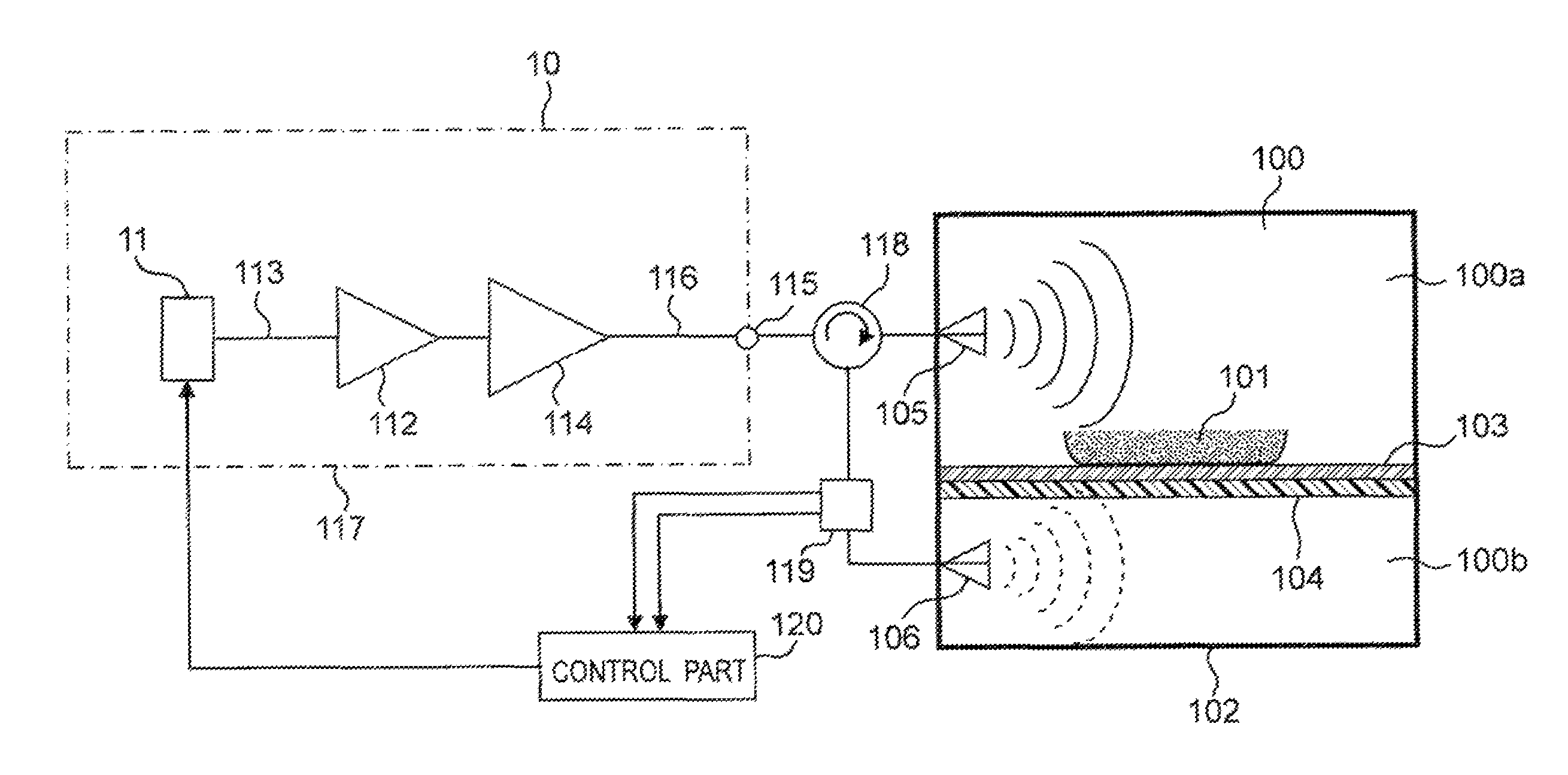
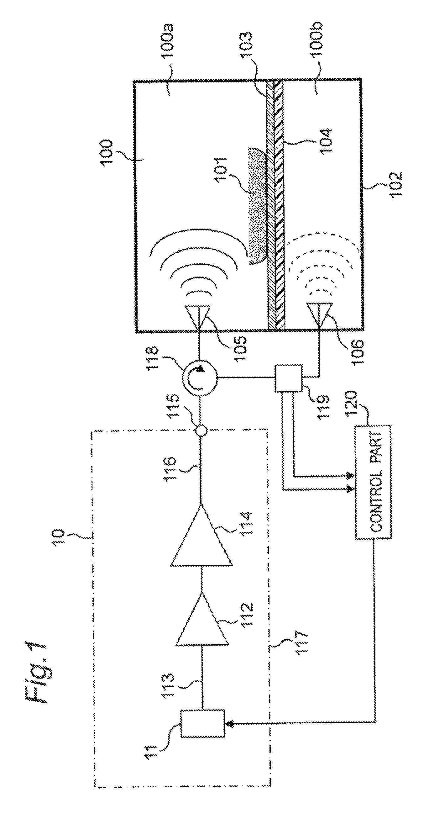
[0053]FIG. 1 is a block diagram showing a configuration of a microwave heating apparatus of a first embodiment according to the present invention.
[0054]As shown in FIG. 1, in the microwave heating apparatus of the first embodiment, a microwave generation part 10 is provided with a microwave oscillation part 11 for generating a microwave, a plurality of steps of microwave amplification parts 112, 114 for amplifying an output of the microwave oscillation part 11, a microwave transmission passage 113 for guiding the output of the microwave oscillation part 11 to the former microwave amplification part 112, and a microwave transmission passage 116 for guiding an output of the main microwave amplification part 114 at a latter stage to an output part 115 of the microwave generation part 10. The microwave oscillation part 11 and the microwave amplification parts 112, 114 are formed with using semiconductor elements. As described above, in the microwave generation part 10,...
second embodiment
(Second Embodiment)
[0116]Hereinafter, a microwave heating apparatus of a second embodiment according to the present invention will be described with reference to attached FIGS. 6 to 10. FIG. 6 is a block diagram showing a configuration of the microwave heating apparatus of the second embodiment. FIG. 7 is a frequency characteristic diagram of the microwave heating apparatus of the second embodiment. FIGS. 8 to 10 are flowcharts showing actions in the microwave heating apparatus of the second embodiment. In the description of the second embodiment, constituent elements having the same functions and configurations as those of the above first embodiment will be given the same symbols, and the description of the first embodiment will be applied to description thereof.
[0117]In FIG. 6, the microwave generation part 10 in the microwave heating apparatus of the second embodiment has the microwave oscillation part 11 formed with using the semiconductor element, a power divider 212 for dividi...
third embodiment
(Third Embodiment)
[0174]Hereinafter, a microwave heating apparatus of a third embodiment according to the present invention will be described with reference to attached FIGS. 11 to 15. FIG. 11 is a block diagram showing a configuration of the microwave heating apparatus of the third embodiment. FIG. 12 is a frequency characteristic diagram of the microwave heating apparatus of the third embodiment. FIGS. 13 to 15 are flowcharts showing actions in the microwave heating apparatus of the third embodiment. In the description of the third embodiment, the constituent elements having the same functions and configurations as those of the above first embodiment will be given the same symbols, and the description of the first embodiment will be applied to description thereof.
[0175]In FIG. 11, the microwave heating apparatus of the third embodiment has two microwave generation parts 10a, 10b. The first microwave generation part 10a has a microwave oscillation part 311 formed with using a semic...
PUM
 Abstract
Description
Claims
Application Information
 - R&D
- Intellectual Property
- Life Sciences
- Materials
- Tech Scout
- Unparalleled Data Quality
- Higher Quality Content
- 60% Fewer Hallucinations
Browse by: Latest US Patents, China's latest patents, Technical Efficacy Thesaurus, Application Domain, Technology Topic, Popular Technical Reports.
© 2025 PatSnap. All rights reserved.Legal|Privacy policy|Modern Slavery Act Transparency Statement|Sitemap|About US| Contact US: help@patsnap.com


