Temperature-compensated oscillator and electronic device

a technology of oscillator and compensating device, which is applied in the direction of oscillator stabilization, oscillator generator, electrical apparatus, etc., can solve the problems of reducing power consumption, frequency change rapidly, and high cost, and achieves accurate temperature compensation, simple configuration, and reduced power consumption

Inactive Publication Date: 2014-03-25
SEIKO EPSON CORP
View PDF17 Cites 2 Cited by
  • Summary
  • Abstract
  • Description
  • Claims
  • Application Information

AI Technical Summary

Benefits of technology

[0027]According to the configuration described above, an electronic device allowing reduction of power consumption with a simple configuration while keeping the accurate temperature compensation can be obtained.

Problems solved by technology

In such temperature-compensated oscillator, there is a problem of reducing the power consumption while keeping the accurate temperature compensation.
However, in the temperature-compensated crystal oscillator of Documents 1 and 3, there are a problem that the frequency changes rapidly due to the change in the capacitance since the change in the capacitance is discrete, and a problem that the cost is too high since it is required to increase the number of capacitors in order to improve the accuracy of the temperature compensation.
Further, since the temperature-compensated crystal oscillator of Document 2 monitors the actual frequency variation to thereby determine whether or not the temperature compensation is to be performed, there is a problem that the configuration for detecting the frequency becomes necessary, which increases the cost.
Further, in Documents 1, 3, and 4, although reduction in power consumption is achieved by changing the period of the timing of outputting the temperature compensation voltage, there is a problem that there is a limitation in reduction in power consumption since the temperature compensation circuit is driven continuously.
Therefore, the temperature compensation voltage becomes discontinuous in the time direction at the switching, which might exert a harmful influence to the voltage-controlled oscillator circuit.

Method used


Image

  • Temperature-compensated oscillator and electronic device
  • Temperature-compensated oscillator and electronic device
  • Temperature-compensated oscillator and electronic device

Examples


Embodiment Construction

[0040]Hereinafter, an embodiment of the invention shown in the accompanying drawings will be explained in detail. It should be noted that constituents, types, combinations, shapes, relative arrangements thereof, and so on described in the present embodiments are not intended to limit the scope of the invention only thereto and are nothing more than mere explanatory examples unless specifically described.

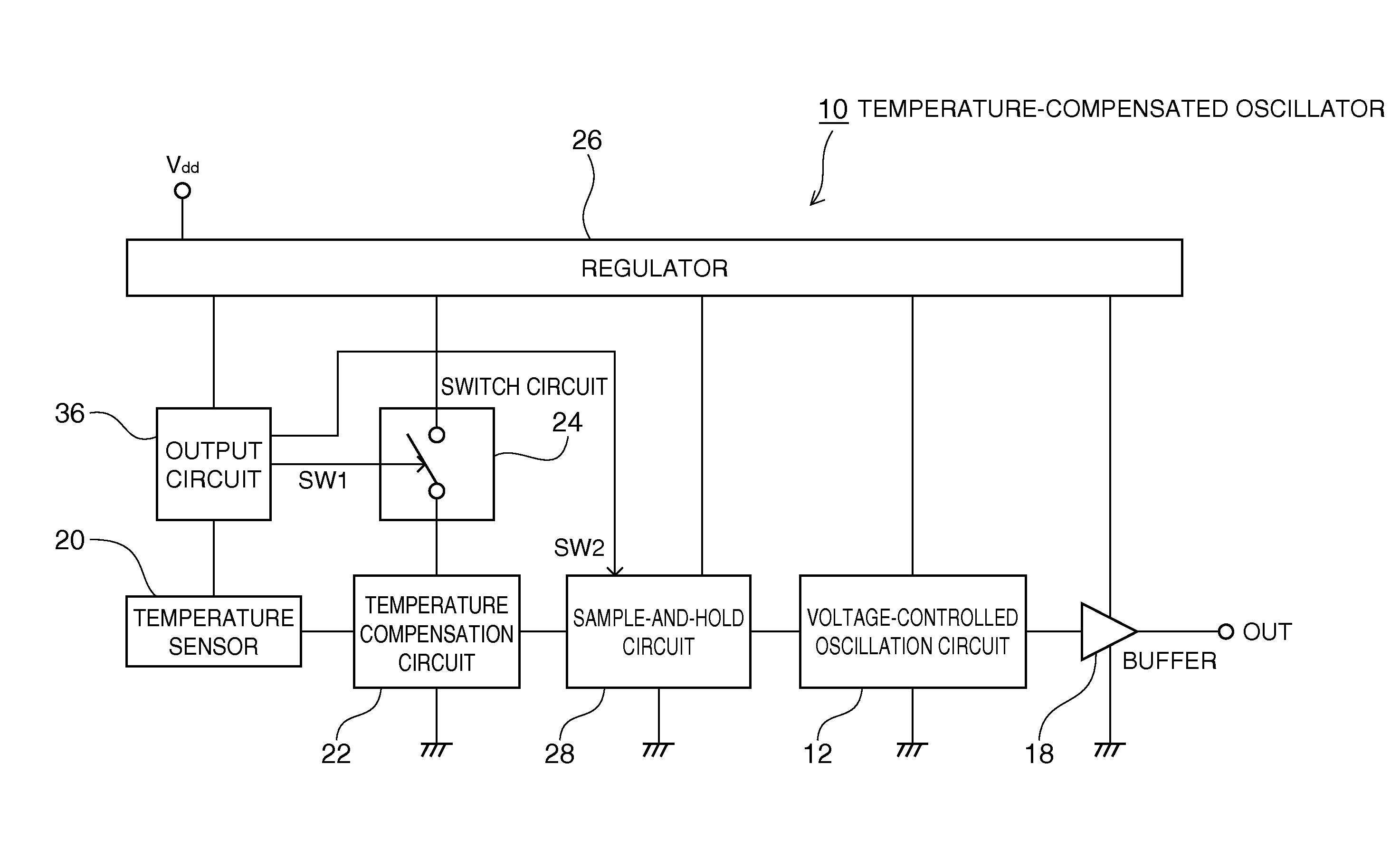
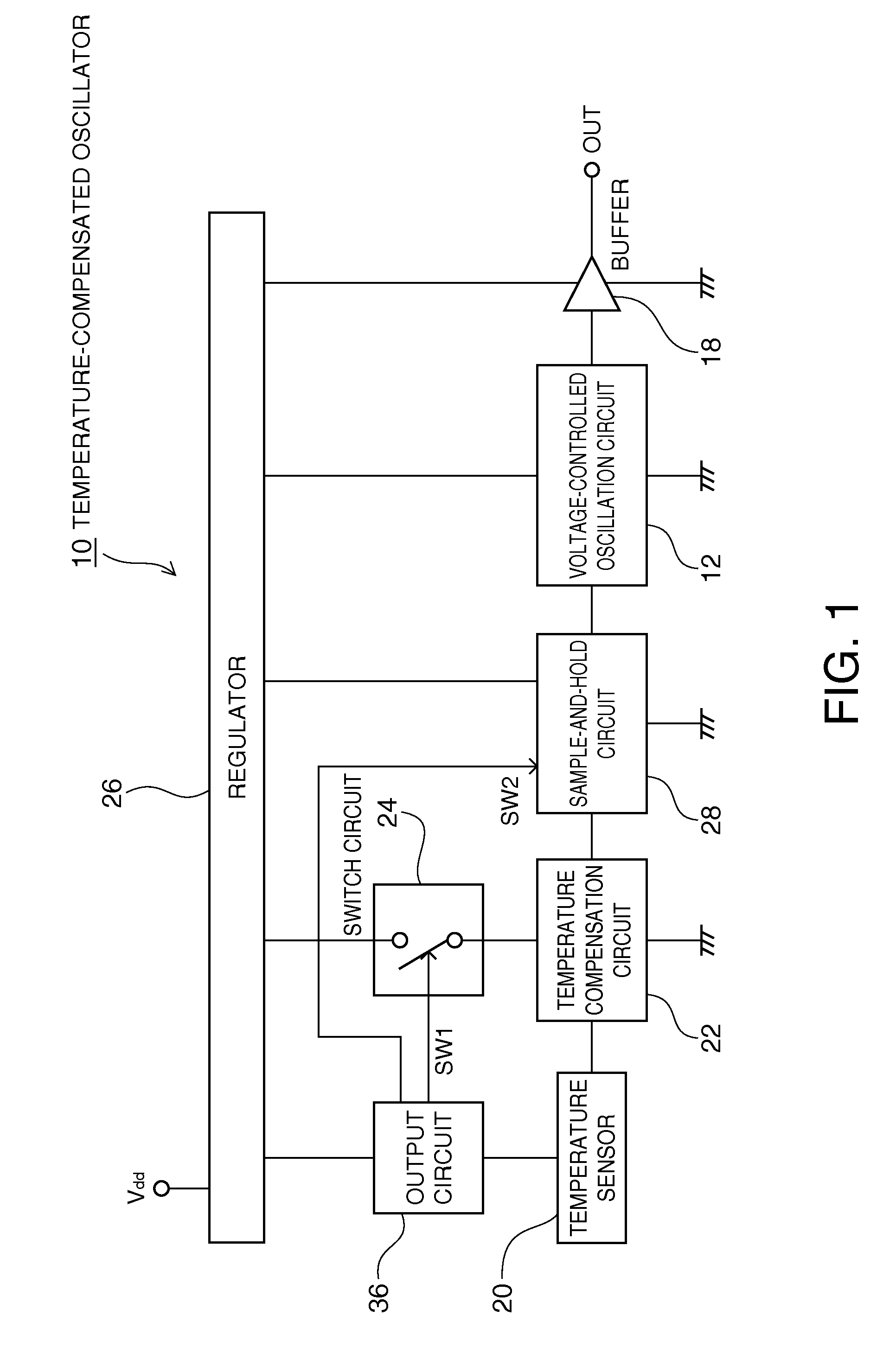
[0041]FIG. 1 shows a general block diagram of a temperature-compensated oscillator according to the present embodiment. The temperature-compensated oscillator 10 according to the present embodiment has a configuration having a temperature sensor 20, a temperature compensation circuit 22, a sample-and-hold circuit 28, a voltage-controlled oscillation circuit 12, and a buffer 18 all connected in series in this order, and further has a regulator (a constant voltage output circuit) 26 for supplying these constituents and an output circuit 36 described later with a constant voltage (elect...


PUM


Abstract

A temperature-compensated oscillator includes a temperature sensor, a temperature compensation circuit, a voltage-controlled oscillation circuit adapted to output an oscillation signal on which temperature compensation is performed based on the temperature compensation voltage, an output circuit adapted to output an ON / OFF signal based on a relationship between variation of the detected-temperature voltage output by the temperature sensor and a reference voltage, a switch circuit adapted to supply the temperature compensation circuit with electrical power in response to the ON / OFF signal, and a sample-and-hold circuit adapted to be switched between a state of outputting the temperature compensation voltage to the voltage-controlled oscillation circuit while holding the temperature compensation voltage output by the temperature compensation circuit, and a state of outputting the temperature compensation voltage held to the voltage-controlled oscillation circuit while cutting the connection to the temperature compensation circuit in response to the ON / OFF signal.

Description

BACKGROUND[0001]1. Technical Field[0002]The present invention relates to a temperature-compensated oscillator allowing reduction of power consumption while keeping the accurate temperature compensation, and an electronic device equipped with the temperature-compensated oscillator.[0003]2. Related Art[0004]In the past, a crystal oscillator such as a temperature-compensated crystal oscillator (TCXO), which is less susceptible to ambient temperature and inherent characteristics of electrical components, and is superior as a stable oscillation circuit, has been used as a reference clock source of an electronic device such as a microcomputer or a cellular phone.[0005]FIG. 11 shows a temperature-compensated crystal oscillator described in JP-A-2003-258551 (Document 1). As shown in FIG. 11, the temperature-compensated oscillator 200 is composed of an oscillation circuit 202 and a temperature compensation circuit 206. The oscillation circuit 202 has a structure in which a plurality of serie...

Claims


Application Information

Patent Timeline
Patent Type & Authority Patents(United States)
IPC IPC(8): H03B5/32H03L1/00
CPCH03L1/022
Inventor TERASAWA, KATSUYOSHI
Owner SEIKO EPSON CORP
Why Eureka
Try Eureka