
Light outputting device and light scanning unit having the same

a scanning unit and light output technology, applied in the direction of semiconductor lasers, laser details, electrical devices, etc., can solve the problems of increased manufacturing cost of light output devices, difficulty in correctly controlling light output, and difficulty in determining wafer growth conditions, so as to minimize the loss of light beams and accurately and automatically control light output.

Inactive Publication Date: 2014-03-25
HEWLETT PACKARD DEV CO LP
View PDF19 Cites 0 Cited by
  • Summary
  • Abstract
  • Description
  • Claims
  • Application Information

AI Technical Summary

Benefits of technology

[0014]Aspects of the present invention provide a light outputting device to accurately and automatically control a light output without being influenced by a divergent angle variation of a light emitted from a VCSEL or a diffused reflection of an external light, and to minimize a loss of a light beam used to monitor the light output of the VCSEL without changing a substrate configuration.
[0015]Another aspect of the present invention provides a light scanning unit to scan a light beam by using at least one VCSEL, and to reduce image inferiority due to a light output difference among multi beams when scanning the multi beams.

Problems solved by technology

Thus, there is a disadvantage that a manufacturing cost of the light outputting device is increased.
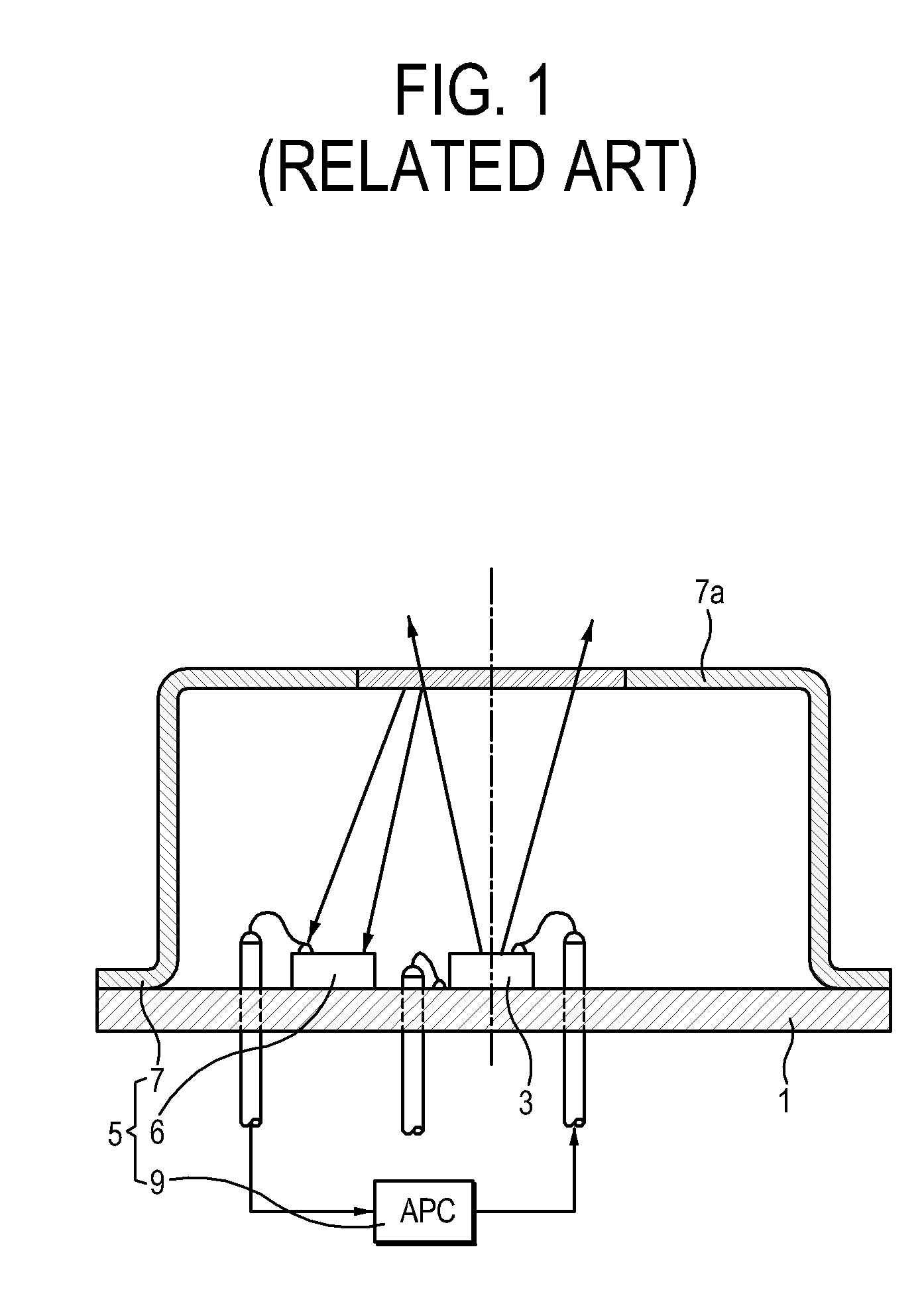
In the light outputting device having the configuration as shown in FIG. 1, since the amount of the light proceeding toward the monitoring detector 6 is not proportional to the amount of the light emitted from the VCSEL 3 due to various “obstructing factors,” it is difficult to correctly control the light output.
In this case, manufacturers may have difficulty in determining a wafer growth condition despite newly manufacturing the substrate.

Method used


Image

  • Light outputting device and light scanning unit having the same
  • Light outputting device and light scanning unit having the same
  • Light outputting device and light scanning unit having the same

Examples


third embodiment

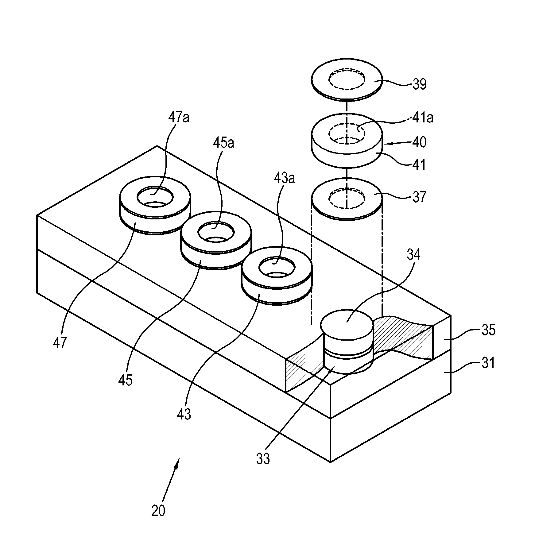
[0068]FIG. 5 is a plane view illustrating a light outputting device 30 according to the present invention. As shown in FIG. 5, the light outputting device 30 includes a substrate 31, a plurality of VCSELs 33 provided on the substrate 31, an isolator 35 electrically and optically isolating each VCSEL 33, and a monitoring detector 50. In comparison with the light outputting device 20 shown in FIG. 3, the monitoring detector 50 of the light outputting device 30 shown in FIG. 5 has a distinct configuration, and other components thereof may have the substantially same configurations as the components described above in connection with the light outputting device 20 shown in FIG. 3.

[0069]The monitoring detector 50 includes at least one light detecting unit 51 to receive lights emitted from at least two light emitting surfaces 34 of each VCSEL 33. FIG. 5 exemplarily illustrates the light outputting device 30 including four VCSELs 33 disposed in a 1×4 arrangement, and a single light detecti...

fifth embodiment

[0073]FIG. 8 is a plane view illustrating a light outputting device 62 according to a fifth exemplary embodiment of the present invention. As shown in FIG. 8, the light outputting device 62 according to the present invention includes a substrate 61, a plurality of VCSELs 63 provided on the substrate 61, an isolator 65 electrically and optically isolating each VCSEL 63, and a monitoring detector 80. In comparison with the light outputting device 30 shown in FIG. 5, the monitoring detector 80 of the light outputting device 62 shown in FIG. 8 has a distinct configuration, and other components thereof may have substantially the same configurations as the configurations of the light outputting device 30 shown in FIG. 5.

[0074]The monitoring detector 80 includes at least one light detecting unit 81 to receive lights emitted from at least two light emitting surfaces 64 of each VCSEL 63. FIG. 8 exemplarily illustrates the light outputting device 62 including four VCSELs 63 disposed in a 1×4 ...


PUM


Abstract

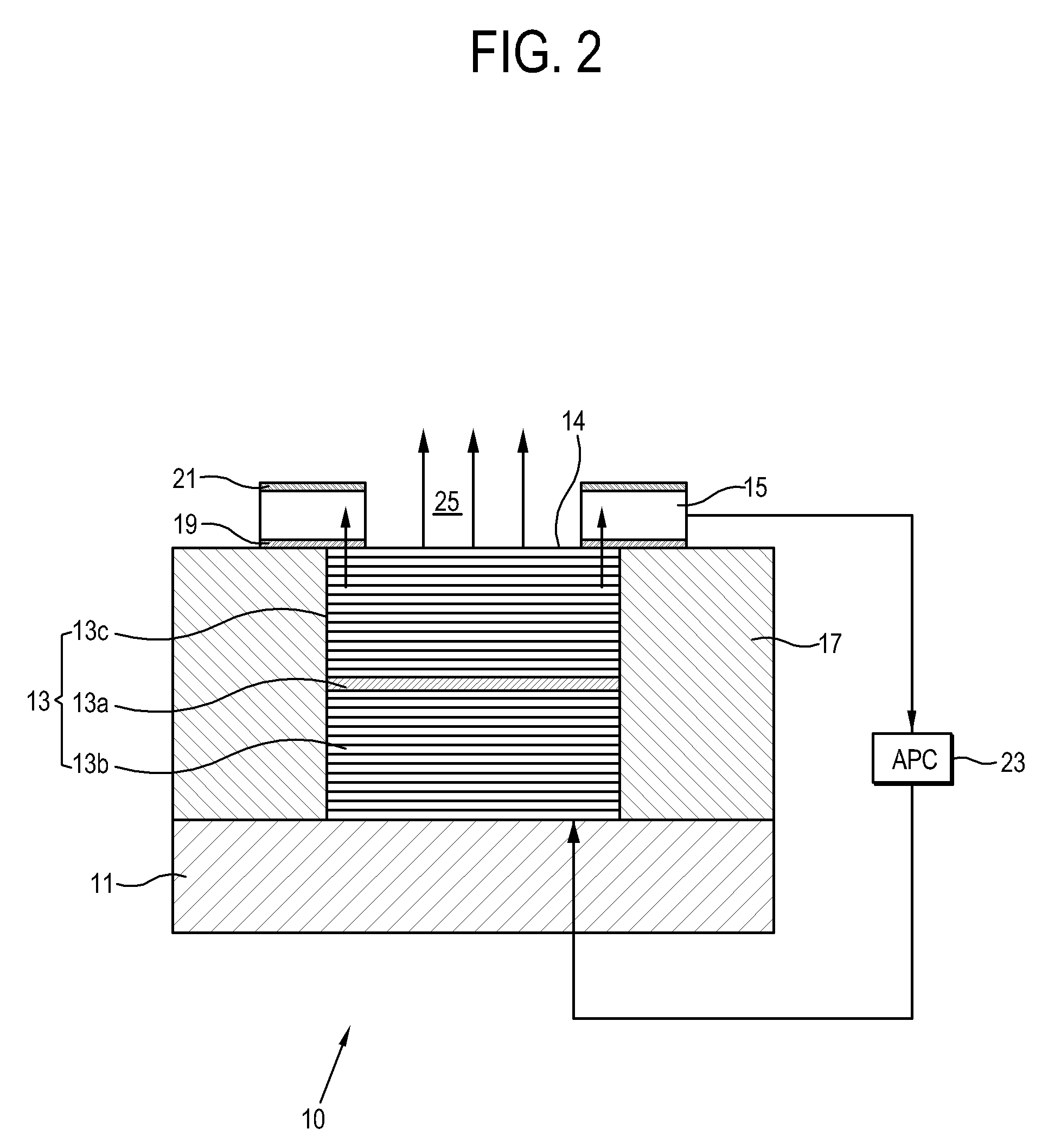
A light outputting device includes, a substrate, a vertical cavity surface emitting laser (VCSEL) provided on a surface of the substrate, including a light emitting surface which emits a light, and a monitoring detector provided on the light emitting surface of the VCSEL to receive a part of the light emitted from the VCSEL so as to monitor the amount of the light emitted from the VCSEL.

Description

CROSS-REFERENCE TO RELATED APPLICATION[0001]This application claims all benefits accruing under 35 U.S.C. §119 from Korean Patent Application No. 2007-94163, filed on Sep. 17, 2007 in the Korean Intellectual Property Office, the disclosure of which is incorporated herein by reference.BACKGROUND OF THE INVENTION[0002]1. Field of the Invention[0003]Aspects of the present invention relate to a light outputting device integrally provided with a monitoring detector and a light scanning unit having the same, and more particularly, to a light outputting device having a compact configuration and an improved ability to detect a signal used to automatically adjust the amount of light emitted from a vertical cavity surface emitting laser (VCSEL) and a light scanning unit having the same.[0004]2. Description of the Related Art[0005]In general, a vertical cavity surface emitting laser (VCSEL) emits a laser beam in a direction through layers of a wafer, that is, in a vertical direction which is p...

Claims


Application Information

Patent Timeline
Patent Type & Authority Patents(United States)
IPC IPC(8): H01S5/00H01S5/026
CPCH01S5/423H01S5/183H01S5/0264H01S5/0262H01S5/4031
Inventor CHOI, JIN-KYUNG
Owner HEWLETT PACKARD DEV CO LP
Learn More