Systems and methods for automated tracker-driven image selection

a tracker-driven, image-driven technology, applied in the field of image-guided surgery, can solve the problems of time-consuming, slow and computationally intensive procedures, and inability to accurately predict the accuracy of the image,

Active Publication Date: 2014-03-25
STRYKER EURO OPERATIONS HLDG LLC
View PDF7 Cites 125 Cited by
  • Summary
  • Abstract
  • Description
  • Claims
  • Application Information

AI Technical Summary

Problems solved by technology

By contrast, fluoroscopic views may be distorted.
The procedure of correlating the lesser quality and non-planar fluoroscopic images with planes in the 3-D image data sets may be time-consuming.
In techniques that use fiducials or added markers, a surgeon may follow a lengthy initialization protocol or a slow and computationally intensive procedure to identify and correlate markers between various sets of images.
Correlation of patient anatomy or intraoperative fluoroscopic images with precompiled 3-D diagnostic image data sets may also be complicated by intervening movement of the imaged structures, particularly soft tissue structures, between the times of original imaging and the intraoperative procedure.
In cases where a growing tumor or evolving condition actually changes the tissue dimension or position between imaging sessions, further confounding factors may appear.
While various jigs and proprietary subassemblies have been devised to make each individual coordinate sensing or image handling system easier to use or reasonably reliable, the field remains unnecessarily complex.
Not only do systems often use correlation of diverse sets of images and extensive point-by-point initialization of the operating, tracking and image space coordinates or features, but systems are subject to constraints due to the proprietary restrictions of diverse hardware manufacturers, the physical limitations imposed by tracking systems and the complex programming task of interfacing with many different image sources in addition to determining their scale, orientation, and relationship to other images and coordinates of the system.
This is a complex undertaking, since the nature of the fluoroscope's 3D to 2D projective imaging results in loss of a great deal of information in each shot, so the reverse transformation is highly underdetermined.
Changes in imaging parameters due to camera and source position and orientation that occur with each shot further complicate the problem.
However, this appears to be computationally very expensive, and the current state of the art suggests that while it may be possible to produce corrected fluoroscopic image data sets with somewhat less costly equipment than that used for conventional CT imaging, intra-operative fluoroscopic image guidance will continue to involve access to MRI, PET or CT data sets, and to rely on extensive surgical input and set-up for tracking systems that allow position or image correlations to be performed.
However, registration using a reference unit located on the patient and away from the fluoroscope camera introduces inaccuracies into coordinate registration due to distance between the reference unit and the fluoroscope.
Additionally, the reference unit located on the patient is typically small or else the unit may interfere with image scanning.
A smaller reference unit may produce less accurate positional measurements, and thus impact registration.
Additionally, surgeons, radiology technologists, and nurses typically spend a significant amount of time identifying appropriate images for navigation or review.
Subsequent retrieval of the appropriate image, particularly during the procedure itself, may be difficult because the images are stored sequentially in time and do not contain any useful identifiers.

Method used


Image

  • Systems and methods for automated tracker-driven image selection
  • Systems and methods for automated tracker-driven image selection
  • Systems and methods for automated tracker-driven image selection

Examples


Embodiment Construction

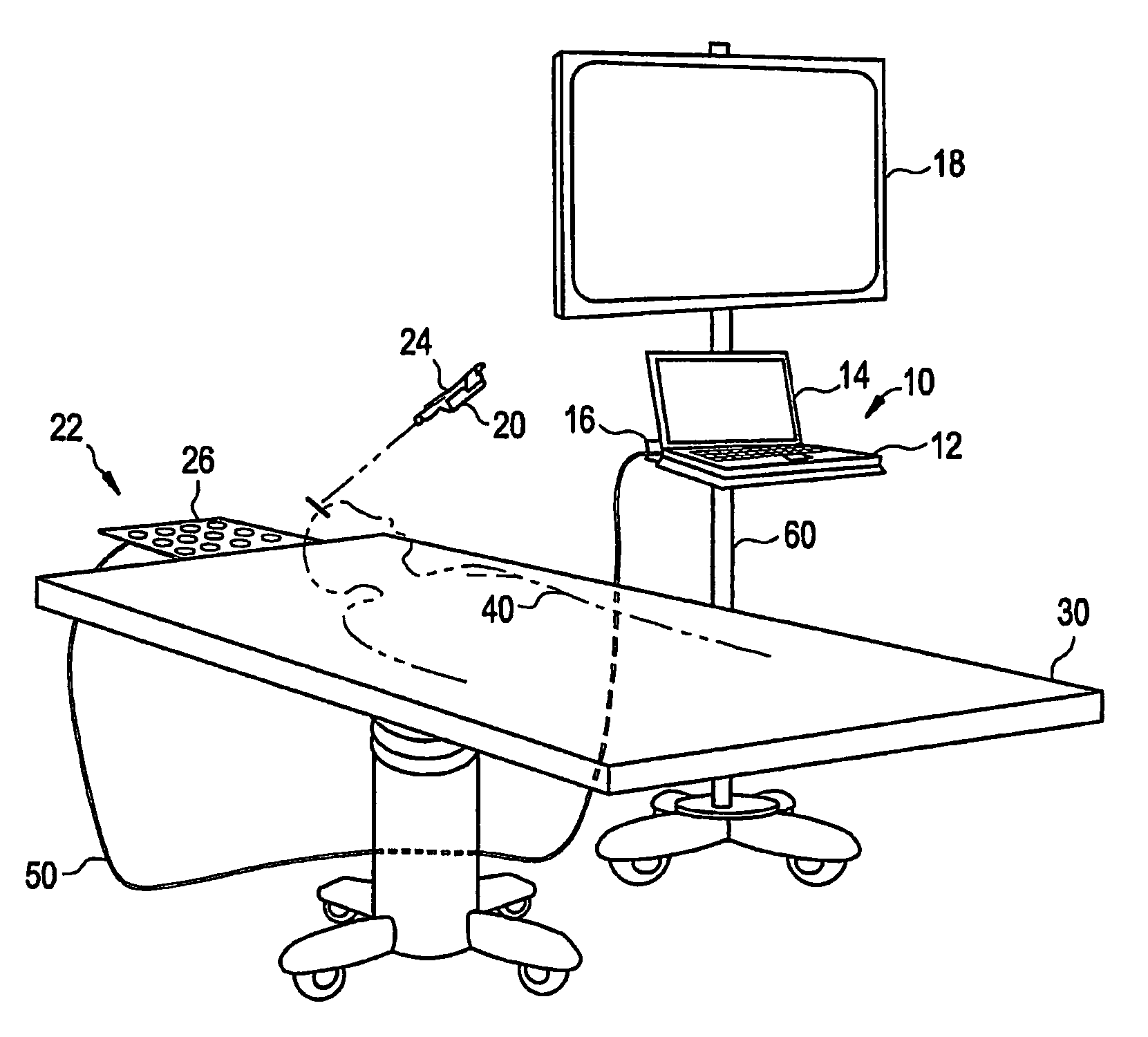
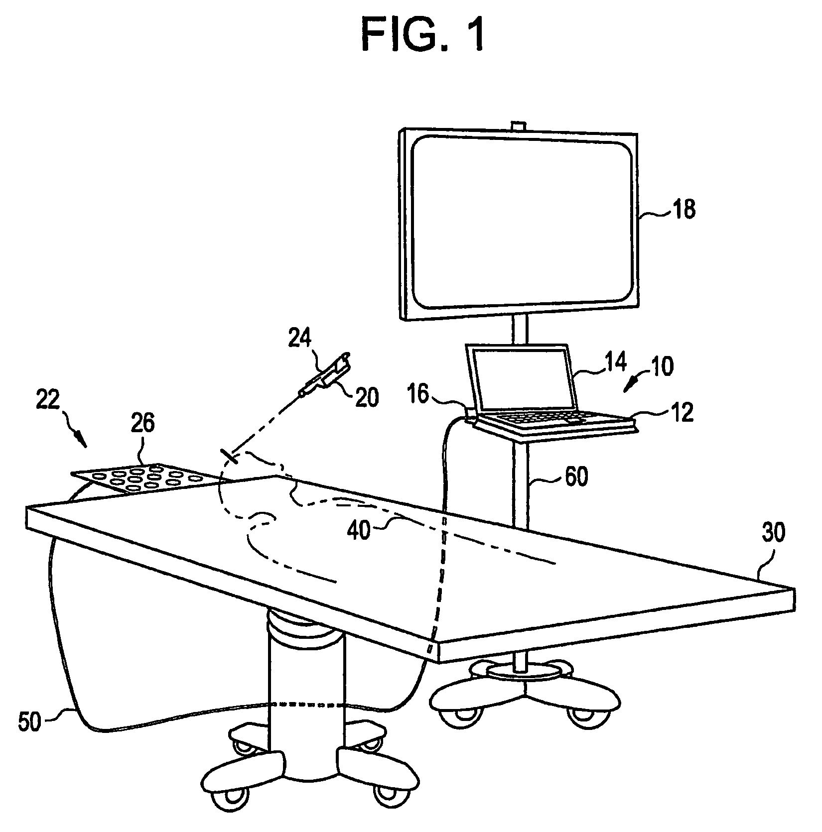
[0037]Referring now to FIG. 1, a medical navigation system (e.g., a surgical navigation system), designated generally by reference numeral 10, is illustrated as including a portable computer 12, a display 14, and a navigation interface 16. The medical navigation system 10 is configured to operate with an electromagnetic field generator 20 and electromagnetic sensor 22 to determine the location of a device 24. Although the system 10 and / or other navigation or tracking system may be used in conjunction with a variety of tracking technologies, including electromagnetic, optical, ultrasound, inertial position and / or other tracking systems, for example, the system 10 is described below with respect to electromagnetic tracking for purposes of illustration only.

[0038]A table 30 is positioned near the electromagnetic sensor 22 to support a patient 40 during a surgical procedure. A cable 50 is provided for the transmission of data between, the electromagnetic sensor 22 and the medical naviga...


PUM


Abstract

Certain embodiments of the present invention provide a method for automated tracker-driven image selection. The method includes determining a location of a tracked device and automatically sorting an image set based at least in part on the location of the tracked device.

Description

RELATED APPLICATIONS[0001][Not Applicable]FEDERALLY SPONSORED RESEARCH OR DEVELOPMENT[0002][Not Applicable]MICROFICHE / COPYRIGHT REFERENCE[0003][Not Applicable]BACKGROUND OF THE INVENTION[0004]The present invention generally relates to image-guided surgery (or surgical navigation). In particular, the present invention relates to systems and methods for automated tracker-driven image selection.[0005]Medical practitioners, such as doctors, surgeons, and other medical professionals, often rely upon technology when performing a medical procedure, such as image-guided surgery or examination. A tracking system may provide positioning information for the medical instrument with respect to the patient or a reference coordinate system, for example. A medical practitioner may refer to the tracking system to ascertain the position of the medical instrument when the instrument is not within the practitioner's line of sight. A tracking system may also aid in pre-surgical planning.[0006]The tracki...

Claims


Application Information

Patent Timeline
Patent Type & Authority Patents(United States)
IPC IPC(8): A61B5/055
CPCA61B19/56A61B6/4441A61B6/4405A61B19/52A61B6/547A61B2019/508A61B19/5244A61B2019/5251A61B2019/5268A61B2019/5289A61B2019/566A61B2019/5238A61B2019/502A61B2034/102A61B90/36A61B2034/2068A61B2034/256A61B34/20A61B34/25A61B2090/364A61B2090/376A61B2034/108A61B2034/2051
Inventor LLOYD, CHARLES, FREDERICK
Owner STRYKER EURO OPERATIONS HLDG LLC
Why Eureka
Try Eureka