
Liquid optics image stabilization

Inactive Publication Date: 2014-04-01
MONUMENT PEAK VENTURES LLC
View PDF104 Cites 12 Cited by
  • Summary
  • Abstract
  • Description
  • Claims
  • Application Information

AI Technical Summary

Benefits of technology

This approach enables efficient image stabilization across various directions and frequencies, including high-frequency vibrations, while also simplifying the lens design and reducing mechanical complexity, allowing for extended zoom ratios and high-performance imaging.

Problems solved by technology

However, these image stabilization devices rely upon mechanical movement of lens elements or sensors.

Method used


Image

  • Liquid optics image stabilization
  • Liquid optics image stabilization
  • Liquid optics image stabilization

Examples


Embodiment Construction

[0030]In the following description of preferred embodiments, reference is made to the accompanying drawings that form a part hereof, and in which is shown by way of illustration specific embodiments in which the invention may be practiced. It is to be understood that other embodiments may be utilized and structural changes may be made without departing from the scope of the invention.

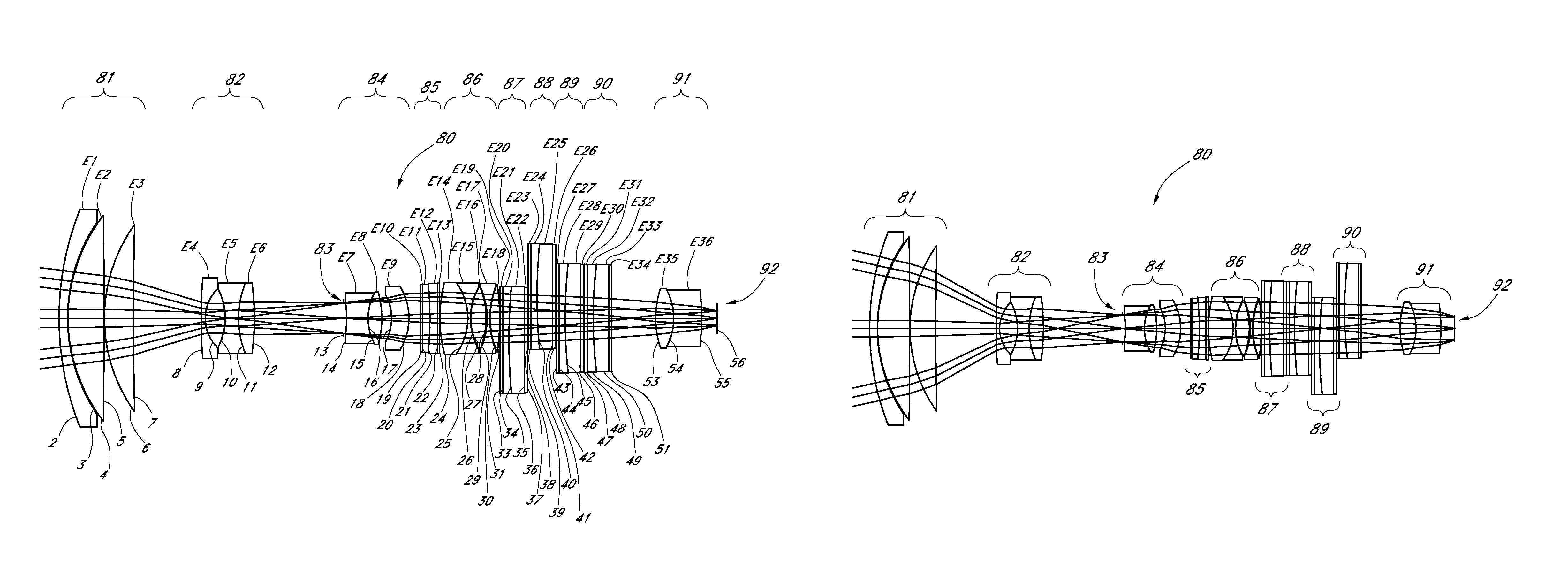
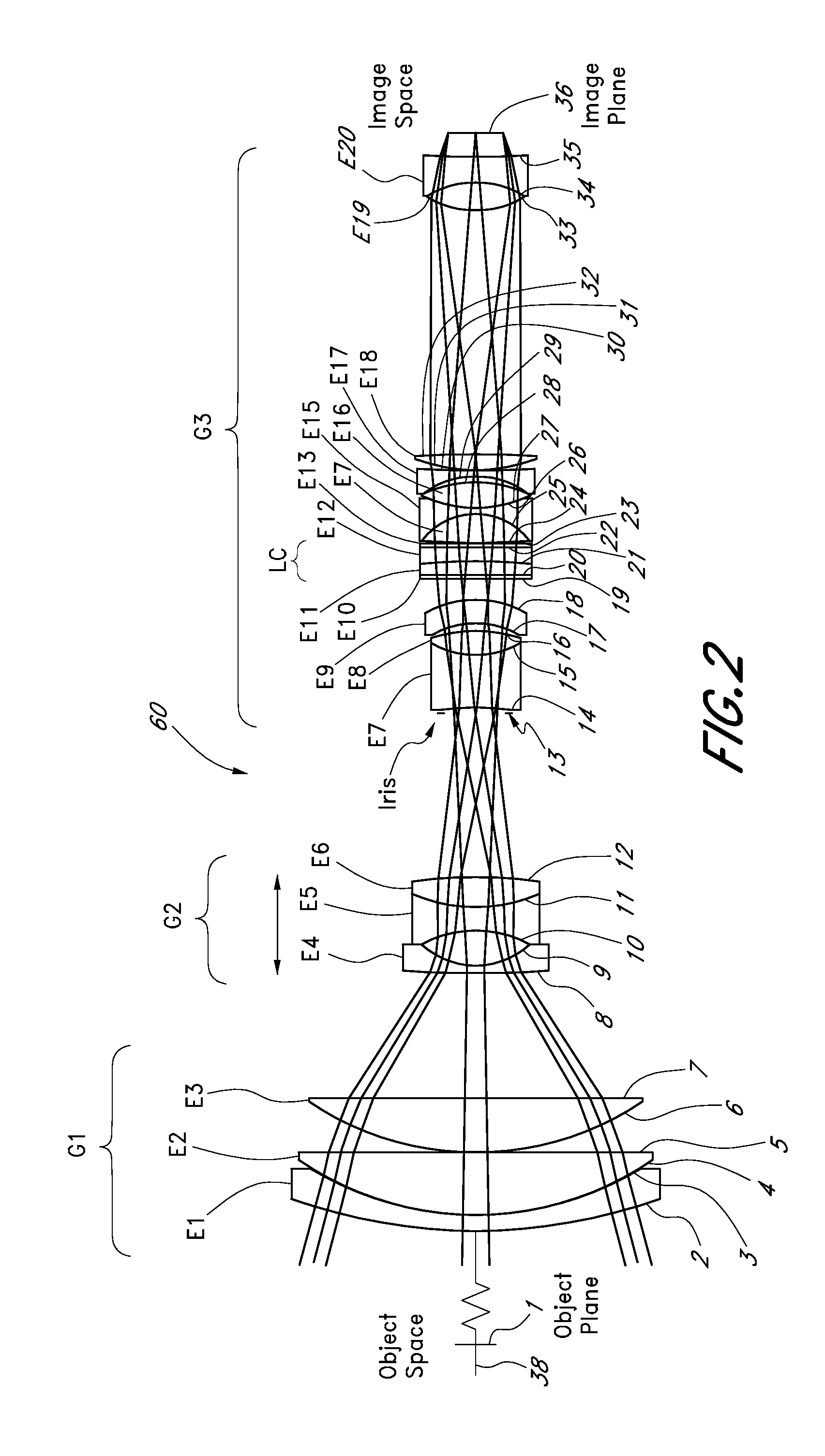
[0031]U.S. Provisional Patent Application No. 60 / 783,338 filed on Oct. 8, 2007 and titled “Liquid Optics Zoom Lens and Imaging Apparatus,” herein incorporated by reference in its entirety, discloses a zoom lens system that employs liquid optics to provide zoom and focus functionality. Liquid optics may also be used to provide stabilization. Exemplary embodiments using liquid optics are disclosed herein.

Liquid Optics in a Zoom Lens System

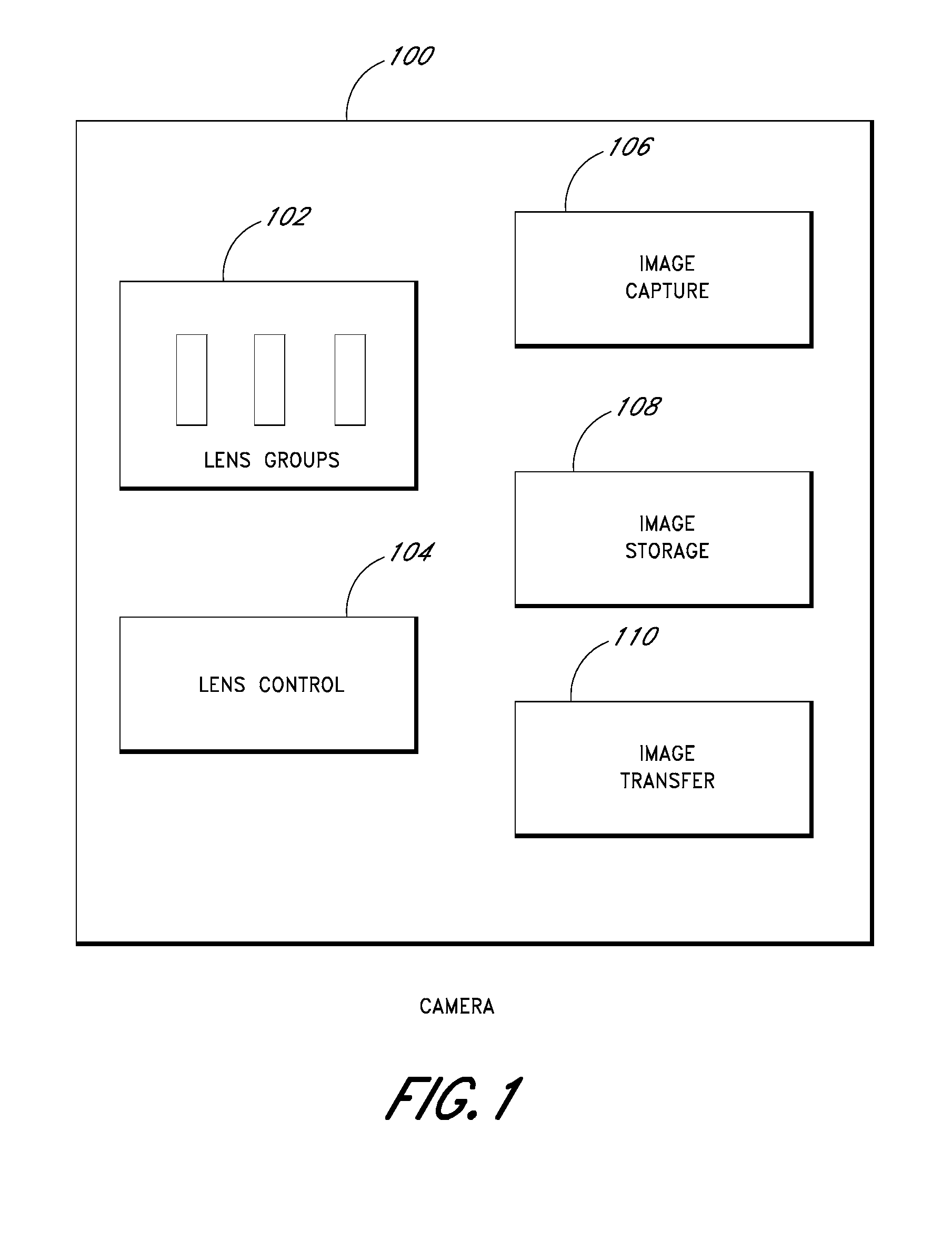
[0032]FIG. 1 illustrates a block diagram of a camera 100 with a zoom lens 102. A zoom lens is an assembly of lens elements with the ability to vary focal length. The ind...


PUM


Abstract

A lens system suitable for use with a camera is disclosed. The lens system employs liquid optics to provide stabilization of an image. A pair of liquid lens cells provides stabilization of the image. A second pair of liquid lens cells may provide stabilization in another direction. The two pairs of liquid cells may provide stabilization in any direction.

Description

RELATED APPLICATIONS[0001]This application is related to, and claims the benefit of U.S. Provisional 60 / 992,284 filed Dec. 4, 2007, the entirety of which is hereby incorporated by reference herein and made a part of the present specification.BACKGROUND[0002]1. Field of the Invention[0003]This invention relates to an optical lens system employing liquid optics to stabilize an image.[0004]2. Description of the Related Art[0005]Optical image stabilization varies an optical path in a lens to stabilize an image reaching a sensor. For example, a floating lens element may be moved orthogonally to the optical axis of the lens. Alternatively, mechanical image stabilization moves the sensor capturing the image to counteract the motion of the camera. However, these image stabilization devices rely upon mechanical movement of lens elements or sensors.SUMMARY[0006]Liquid lens cells can modify an optical path without relying upon mechanical movement of the liquid cell, thereby providing vibration...

Claims


Application Information

Patent Timeline
Patent Type & Authority Patents(United States)
IPC IPC(8): G02B27/64G02B3/14
CPCG02B26/004G02B27/646G02B3/14G02B15/143105
Inventor JANNARD, JAMES H.NEIL, IAIN
Owner MONUMENT PEAK VENTURES LLC
Learn More