RFID tag supplying apparatus and tag tape roll
- Summary
- Abstract
- Description
- Claims
- Application Information
AI Technical Summary
Benefits of technology
Problems solved by technology
Method used
Image
Examples
first embodiment
[0080]In the following, some embodiments of the present disclosure will be described with reference to the accompanying drawings. the present disclosure is first described below.
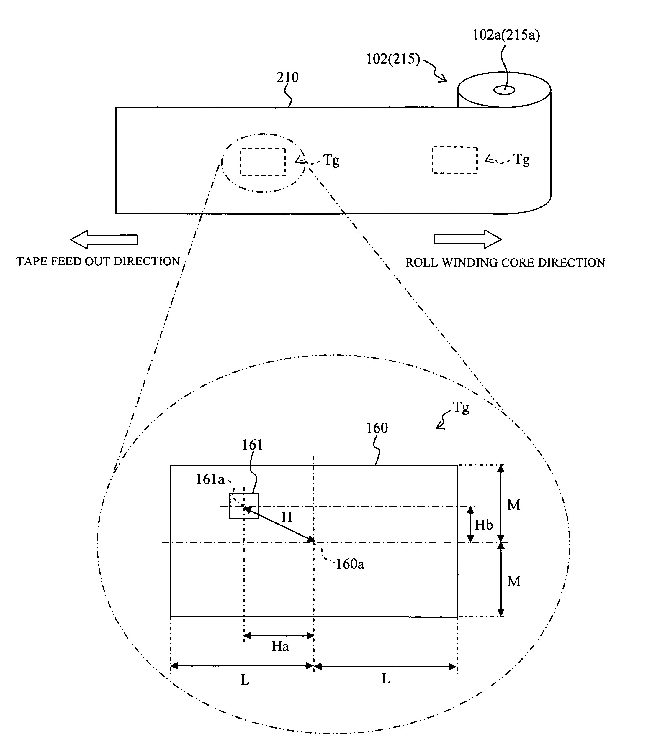
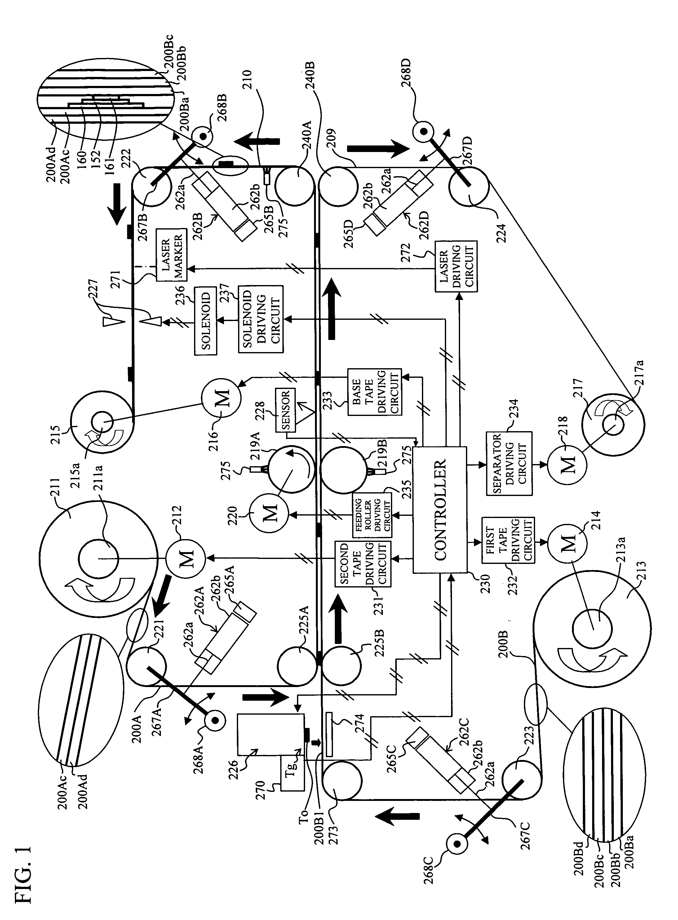
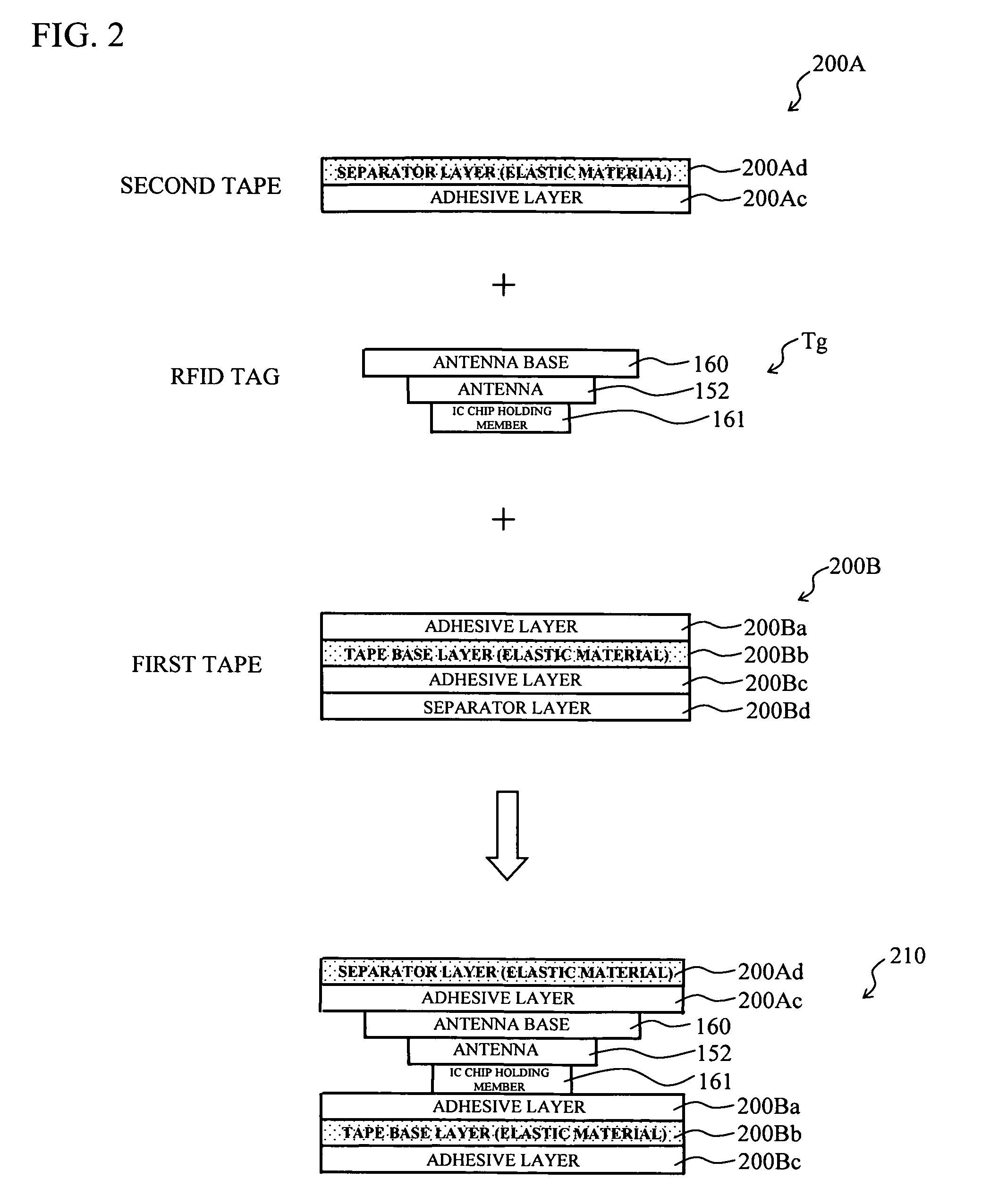
[0081]FIG. 1 is a conceptual diagram briefly showing an overall general structure of a tag tape roll manufacturing apparatus of the present embodiment. In FIG. 1, the tag tape roll manufacturing apparatus produces a base tape 210 by inserting bonding a second tape 200A (structural details are discussed later) and a first tape 200B (structural details are discussed later) and inserting an RFID tag Tg which is provided with an RFID circuit element To inserted between the two tapes, and manufactures a base tape roll 215 by winding the base tape 210.
[0082]That is, the tag tape manufacturing apparatus has a second tape roll 211 formed by the wound second tape 200A, a second tape shaft driving motor 212 for driving the second tape roll 211, a first tape roll 214 formed by the wound first tape 200B, a second tape s...
second embodiment
[0223]Note that although the tension control adds tension in the pulling direction of the first tape 200B as described above, the disclosure is not limited to this arrangement inasmuch as tension may be added to both the first tape 200B and the second tape 200A to provide a tension difference between the tension added to the first tape 200B and the tension added to the second tape 200A. In this case the tension added to the first tape 200B is greater than the tension added to the second tape 200A, and is controlled to a suitable value to lengthen the first tape 200B to be longer than the second tape 200A by the amount 2πt. In this case as well, similar advantages to those of the second embodiment are provided.
[0224]Tension control for reducing the tension in the pulling direction may be performed as the position in the diameter direction of the roll become farther from the center in the diameter direction, and tension control for increasing tension in the pulling direction may be pe...
third embodiment
[0227]The following describes the present disclosure with reference to accompanying drawings.
[0228]FIG. 37 is a conceptual diagram showing an overall general structure of the tag tape roll manufacturing apparatus according to the present embodiment, and corresponds to FIG. 1 described above. FIG. 38 is a conceptual side view showing the condition the first tape 200B and the second tape 200A are bonded with the RFID tag Tg interposed therebetween in the present embodiment, and corresponds to FIGS. 2 and 5 above. Note that parts in FIGS. 1, 2, and 5 similar to parts in FIGS. 37 and 38 have the same reference number, and are not described further.
[0229]In FIGS. 37 and 38 the second tape 200A has a four-layer structure similar to FIG. 5 configured by sequentially laminating a separator layer 200Ad, adhesive layer 200Ac formed of a suitable adhesive, tape base layer 200Ab, and adhesive layer 200Aa. The first tape 200B also has a four-layer structure similar to FIG. 5 configured by sequen...
PUM
| Property | Measurement | Unit |
|---|---|---|
| Volume | aaaaa | aaaaa |
| Length | aaaaa | aaaaa |
| Length | aaaaa | aaaaa |
Abstract
Description
Claims
Application Information
 - R&D
- Intellectual Property
- Life Sciences
- Materials
- Tech Scout
- Unparalleled Data Quality
- Higher Quality Content
- 60% Fewer Hallucinations
Browse by: Latest US Patents, China's latest patents, Technical Efficacy Thesaurus, Application Domain, Technology Topic, Popular Technical Reports.
© 2025 PatSnap. All rights reserved.Legal|Privacy policy|Modern Slavery Act Transparency Statement|Sitemap|About US| Contact US: help@patsnap.com


