

Nameplate attachment structure, camera platform apparatus, and camera apparatus
- Summary
- Abstract
- Description
- Claims
- Application Information
AI Technical Summary
Benefits of technology
Problems solved by technology
Method used
Image

Examples
first embodiment
[0024](First Embodiment)
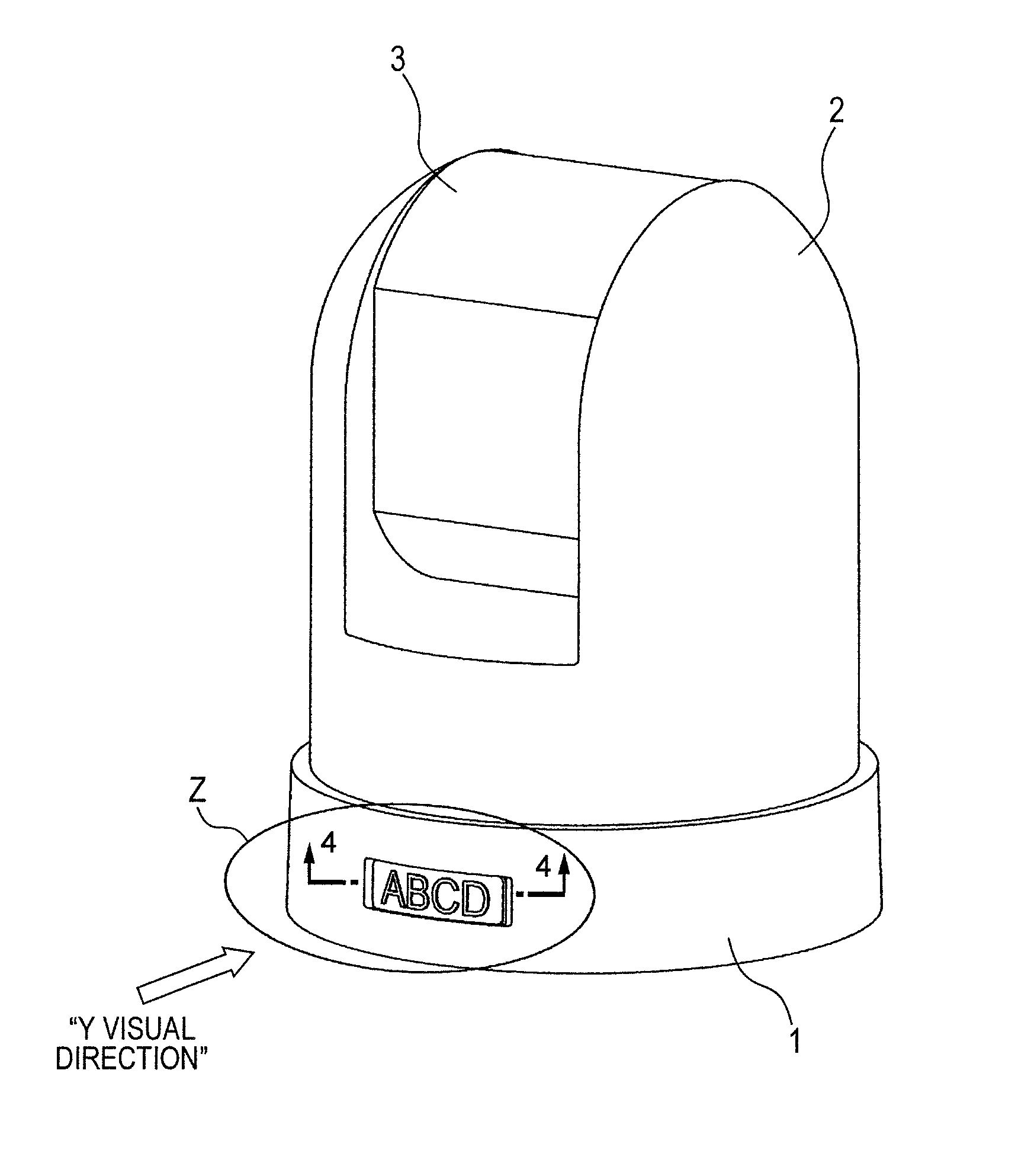
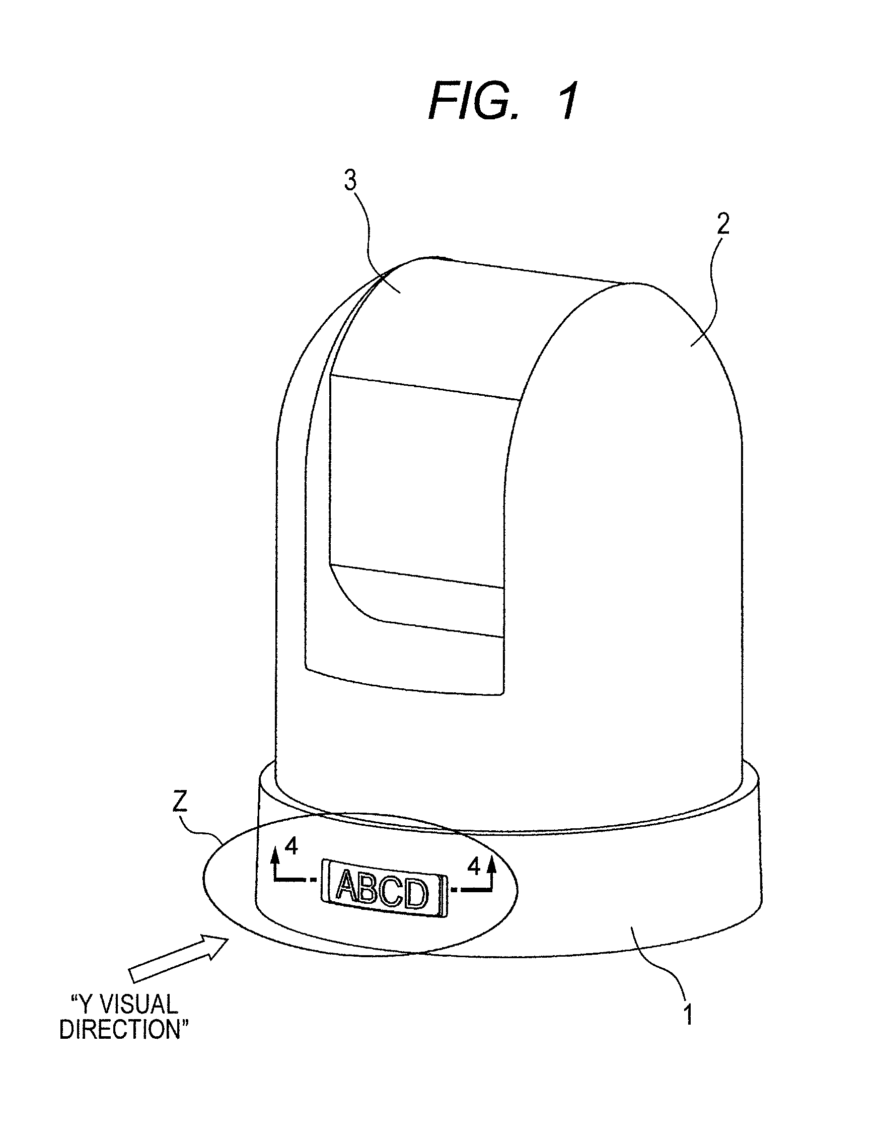
[0025]In the following, with reference to FIGS. 1 to 9, a nameplate attachment structure according to a first embodiment of the present invention is described. FIG. 1 is a perspective view of a camera platform apparatus provided with the nameplate attachment structure according to the first embodiment of the present invention. A head 2 is attached to a base 1 supported by a tripod (not shown) or the like so as to be pivotable in a horizontal direction, and a housing 3 having an image pickup apparatus mounted thereto is attached to the head 2 so as to be pivotable in a perpendicular direction. The base 1 is provided with a directional indication unit Z indicating information, a picture, a shape, and the like. The base 1, the head 2, the housing 3, and the image pickup apparatus mounted to the housing 3 form a camera apparatus.
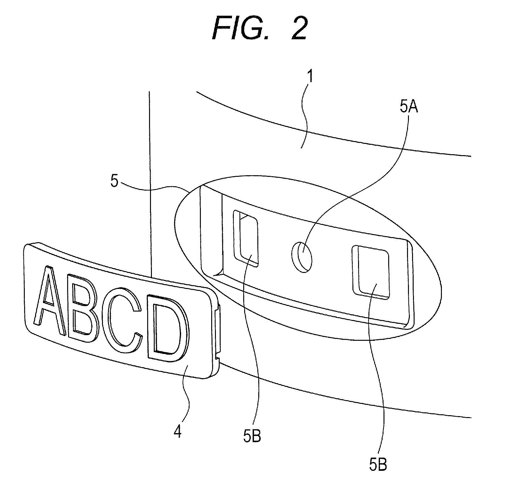
[0026]FIG. 2 is an exploded perspective view of the indication unit Z, which is viewed from a Y visual direction of FIG. 1. FIG. 3 is an...
second embodiment
[0038](Second Embodiment)
[0039]In the following, with reference to FIGS. 10 and 11, a nameplate attachment structure according to a second embodiment of the present invention is described. This embodiment is a modified example of the first embodiment and the same positions and components as those of the second embodiment are represented by the same reference symbols, and detailed description thereof is therefore omitted herein.
[0040]FIG. 10 is a perspective view of a nameplate 41 and a containing unit 51 viewed from the same direction as that in FIG. 2 of the first embodiment. FIG. 11 illustrates a structure of FIG. 10 in a view from the inside of the base 1. As illustrated in FIG. 11, on a rear side of an indication-present surface of the nameplate 41, engagement pieces 41C respectively provided with hook projections 41B are formed at four positions. The four positions are provided at equal intervals about a shaft 41A, specifically, an angular relationship of 90 degrees is maintain...
PUM
 Abstract
Description
Claims
Application Information