Method and apparatus for vibrating a flow tube of a vibrating flow meter

a flow meter and flow tube technology, applied in the field of vibrating flow meters, can solve the problems of increasing the complexity of the type of drive signal, the inability to achieve a typical driver, and the prohibitive weight of the magnets attached to the flow tubes

Active Publication Date: 2014-04-15
MICRO MOTION INC
View PDF22 Cites 14 Cited by
  • Summary
  • Abstract
  • Description
  • Claims
  • Application Information

AI Technical Summary

Problems solved by technology

In certain applications, the typical driver may not be feasible.
This is particularly true in low flow applications where the weight of the magnets attached to the flow tubes becomes prohibitive.
Recently however, the type of drive signal has become more complex than a simple square, trapezoidal, sinusoidal single-frequency drive signal.
To implement advanced flow meter functions such as meter verification, speed of sound measurements, multiphase flow detection, etc., multiple frequencies are imposed on the flow tubes simultaneously resulting in a complex drive signal.
Such a drive force may not be a problem in typical driver assemblies, however, in implementations such as disclosed in the '329 patent, the flow meter can only operate in either a pull-mode or a push-mode.
This configuration requires an excessive number of parts, which can be costly.
Although most vibratory flow meters are built with a linear drive system, some flow meters, such as the flow meters mentioned in the '329 patent lack a linear drive signal and therefore, generally cannot support complex drive signals.
These solutions are expensive and may be prohibitive in terms of size and power constraints.

Method used


Image

  • Method and apparatus for vibrating a flow tube of a vibrating flow meter
  • Method and apparatus for vibrating a flow tube of a vibrating flow meter
  • Method and apparatus for vibrating a flow tube of a vibrating flow meter

Examples


Embodiment Construction

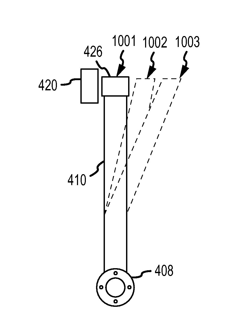
[0051]FIGS. 4-15 and the following description depict specific examples to teach those skilled in the art how to make and use the best mode of the invention. For the purpose of teaching inventive principles, some conventional aspects have been simplified or omitted. Those skilled in the art will appreciate variations from these examples that fall within the scope of the invention. Those skilled in the art will appreciate that the features described below can be combined in various ways to form multiple variations of the invention. As a result, the invention is not limited to the specific examples described below, but only by the claims and their equivalents.

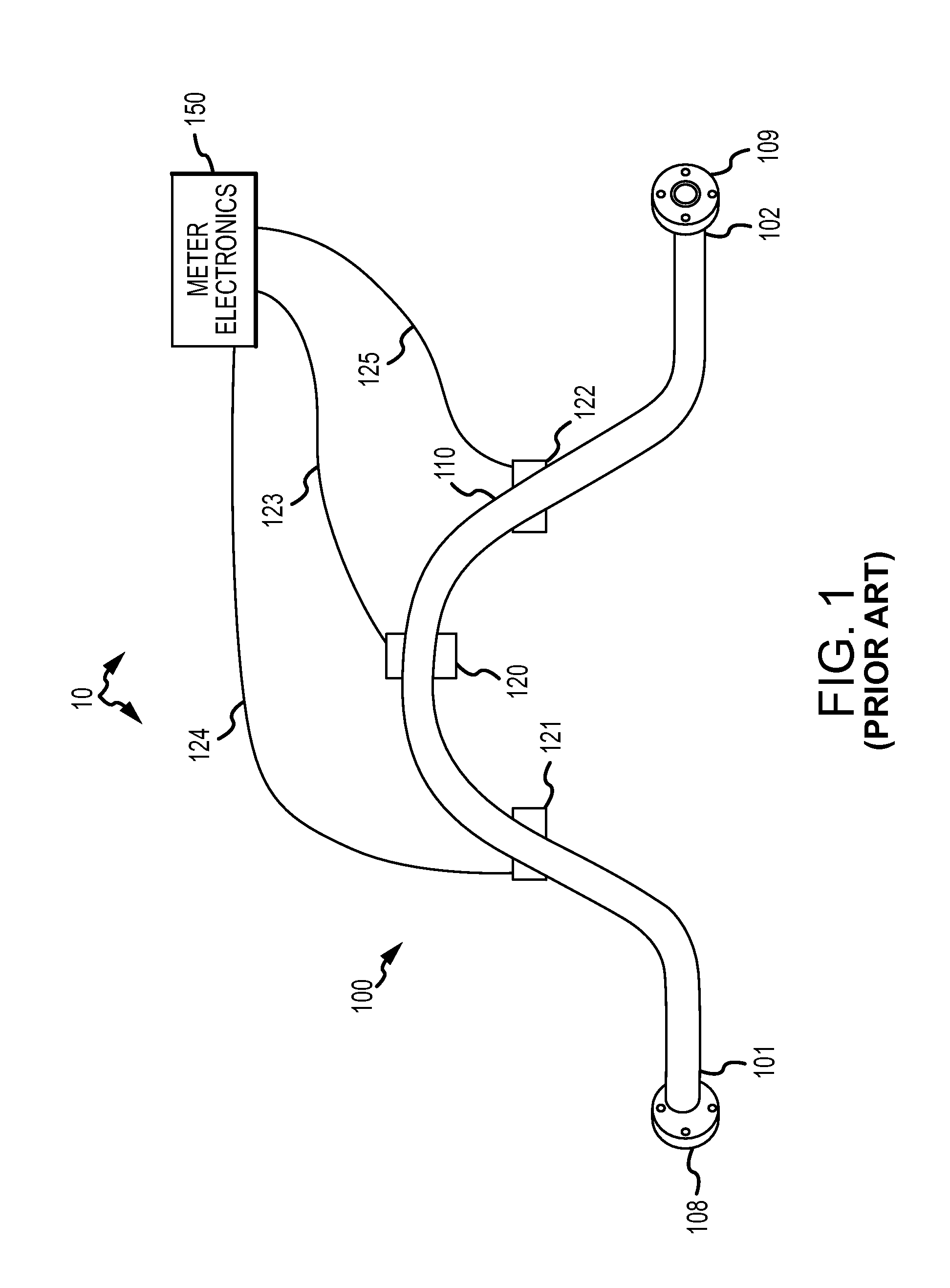
[0052]FIG. 1 shows a prior art flow measurement system 10. The flow measurement system 10 includes a vibratory flow meter 100 and a meter electronics 150. The flow meter 100 includes a flow tube 110, a driver 120, and pick-off sensors 121, 122. The driver 120 and the pick-off sensors 121, 122 can communicate with the meter electr...


PUM


Abstract

A flow measurement system (20) is provided according to an embodiment of the invention. The flow measurement system (20) comprises a vibrating flow meter (400) including at least one flow tube (410) and a driver (420) adapted to apply a biasing force on the flow tube (410). The flow measurement system (20) also comprises a meter electronics (450) configured to generate a drive signal to vibrate the flow tube (410) about a first deflected position (1002), wherein the first deflected position (1002) is offset from a flow tube rest position (1001).

Description

TECHNICAL FIELD[0001]The present invention relates to vibrating flow meters, and more particularly, to a method and apparatus for vibrating a flow tube of a vibrating flow meter.BACKGROUND OF THE INVENTION[0002]Flow meters are used to measure the mass flow rate, density, and other characteristics of flowing materials. The flowing material may comprise a liquid, gas, solids suspended in liquids or gas, or any combination thereof. Vibrating conduit sensors, such as Coriolis mass flow meters and vibrating densitometers typically operate by detecting motion of a vibrating conduit that contains a flowing material. Properties associated with the material in the conduit, such as mass flow, density and the like, can be determined by processing measurement signals received from motion transducers associated with the conduit. The vibration modes of the vibrating material-filled system generally are affected by the combined mass, stiffness, and damping characteristics of the containing conduit...

Claims


Application Information

Patent Timeline
Patent Type & Authority Patents(United States)
IPC IPC(8): G01F1/84
CPCG01F1/8472G01F1/84
Inventor HAYS, PAUL JKRAVITZ, ANDREW STEPHEN
Owner MICRO MOTION INC
Why Eureka
Try Eureka