Plasma sterilizing device and method

a sterilizing device and plasma technology, applied in the field of plasma sterilizing devices and methods, can solve the problems of low sterilization efficiency, material quality change, poisonous ethylene oxide and hydrogen peroxide, etc., and achieve the effect of effective sterilization process, efficient use, and effective decomposition and removal of bacteria

Inactive Publication Date: 2014-04-15
SAGA UNIVERSITY
View PDF12 Cites 0 Cited by
  • Summary
  • Abstract
  • Description
  • Claims
  • Application Information

AI Technical Summary

Benefits of technology

[0029]In accordance with the invention according to Claim 1, an alternating current voltage is applied to an electrode provided at least one end of the long tubule in such a state that the pressure inside or outside the long tubule can be adjusted so that there is a predetermined difference in pressure, and thus, it becomes possible to generate plasma inside the long tubule. As a result, there is glow discharge within the long tubule but no discharge outside the long tubule. Because of the plasma inside the long tubule, it becomes possible to effectively decompose and remove bacteria that cling to the inner wall of the tubule. In particular, the air pressure remains unsuitable for glow discharge outside the long tubule, and therefore there is no discharge, and it becomes possible to generate plasma inside the long tubule by efficiently using the power supplied to the electrode.
[0030]When plasma is generated, not only electrons and ions but also ultraviolet rays and radicals are generated. It becomes possible to effectively carry out a sterilizing process using plasma or substances generated as byproducts, so that viruses and bacteria are killed or destroyed and proteins and lipids are neutralized, decomposed and removed. Bacteria are physically destroyed due to ion impulses in the plasma, DNA is destroyed by ultraviolet rays, and the surface of bacteria is etched by radical atoms and molecules, such as oxygen radicals or OH radicals, for example.
[0031]Furthermore, In accordance with the present invention, no member is inserted deep into the long tubule, and therefore, a sterilizing process can be carried out even in the case where the inner diameter of the long tubule is 5 mm or less, and in addition, it becomes possible to prevent the inner wall from being damaged, as well as secondary infection. Furthermore, the sputtering electrode does not adhere to the inner wall of the long tubule, and the glow discharge used in the present invention makes it possible to prevent the electrode from sputtering when plasma is generated under atmospheric pressure.
[0032]In accordance with the invention according to Claim 2, in the case where the second electrode that faces the first electrode provided at one end is an electrode provided at the other end of the long tubule, the second electrode is easy to attach at the other end of the long tubule in the same manner as the first electrode, and therefore, less work is required than in conventional sterilizing processes, where the electrode is provided within the tubule, and there are no problems with the tubule being damaged. In addition, in the case where the second electrode is a wall of the container, no work is required to attach the second electrode to the long tubule.
[0033]In accordance with the invention according to Claim 3, a through hole for making conduction between the inside and outside of the long tubule is created in one of the electrodes provided at an end of the long tubule, and therefore, it is possible to introduce a gas in the long tubule or discharge it, through the through hole. In addition, it is possible to keep a predetermined difference in pressure between the inside and outside of any tubule of any diameter by adjusting the diameter of the through hole, and thus, it is possible to generate plasma efficiently inside the tubule.
[0034]In accordance with the invention according to Claim 4, at least a gas supplying means or a gas discharging means is connected to the through hole so that a gas can enter and leave the long tubule through the through hole created in the electrode, and therefore, it is possible to forcibly change the gas within the long tubule. As a result, it becomes possible to introduce a gas that is appropriate for the sterilizing process, such as argon gas, which is easy to convert to plasma or oxygen gas, which is highly effective as a sterilizer into the long tubule, as well as to discharge the gas generated in the sterilizing process from the long tubule.

Problems solved by technology

Though according to some conventional methods for sterilizing long tubules, such as catheters and endoscopes, ultraviolet rays or high pressure steam is used, the efficiency of sterilization is low, and in some cases the material changes in quality due to the ultraviolet rays or heat.
Though other conventional methods using ethylene oxide gas, liquid hydrogen peroxide and steam are highly effective, ethylene oxide and hydrogen peroxide are poisonous, and hydrogen peroxide can be harmful to the handler if it gets on the clothes.
In addition, liquids and gases do not reach deep inside the long tubule, due to their viscosity, in accordance with methods other than those using ethylene oxide, and ultraviolet rays are insufficiently transmissive to do so, and thus, it is difficult to sufficiently sterilize long tubules.
However, it is difficult to make the outer and inner diameter of the discharge wire small in order to avoid conduction between the center electrode and the external electrode and secure a space for discharge between the two, and it is also necessary for the wire to be thick enough, and for insulation between the wires to be secured in order to prevent insulation breakdown in the electricity supply wire.
Thus, the long tubules to be sterilized are limited to those having a large inner diameter (for example of 5 mm or more, or 1 cm or more), and in addition, the inner wall of long tubules easily scratches when the discharge wire and electricity supply wire are inserted and removed.
Furthermore, when the discharge wire or electricity supply wire makes contact with the inner wall after the sterilization process, bacteria and the like on the surface stick to the inner wall, causing secondary infection.
In the case where the same device is used for sterilization, secondary infection becomes a significant problem.
As in the case of the above described Patent Document 1, however, the insertion of a wire electrode into the tubule risks damaging the inside or causing secondary infection.
In addition, there is a risk that the wire electrode may sputter because of the plasma, or that the metal that forms the electrode may make contact with the inside of the tubule along the entire length and causing contamination.
Therefore, a moving mechanism or the like is required in order to move the tubule and the electrodes relative to each other and sterilize the entirety of the inside, making the structure complex and increasing the risk of the inside or outside of the tubule getting damaged, as well as secondary infection.
In addition, there is a risk that the outside of the tubule may be damaged or infected, because the tubule and the grounding electrode are close to each other.
Even in the case where the diameter of the grounding electrode is large enough to accommodate for tubules of different diameters, the distance between the wire electrode and the grounding electrode is great, and thus the voltage to be applied to the electrode is high, and as a result, there is a high risk that the wire electrode or the grounding electrode may sputter because of the plasma and contaminate the tubule.

Method used


Image

  • Plasma sterilizing device and method
  • Plasma sterilizing device and method
  • Plasma sterilizing device and method

Examples


embodiments

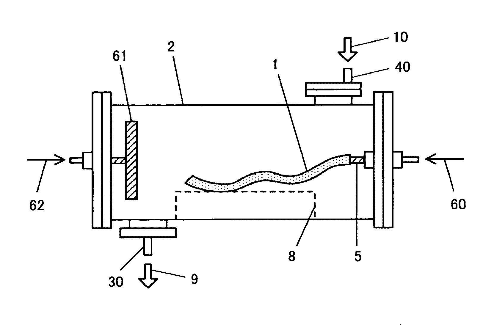
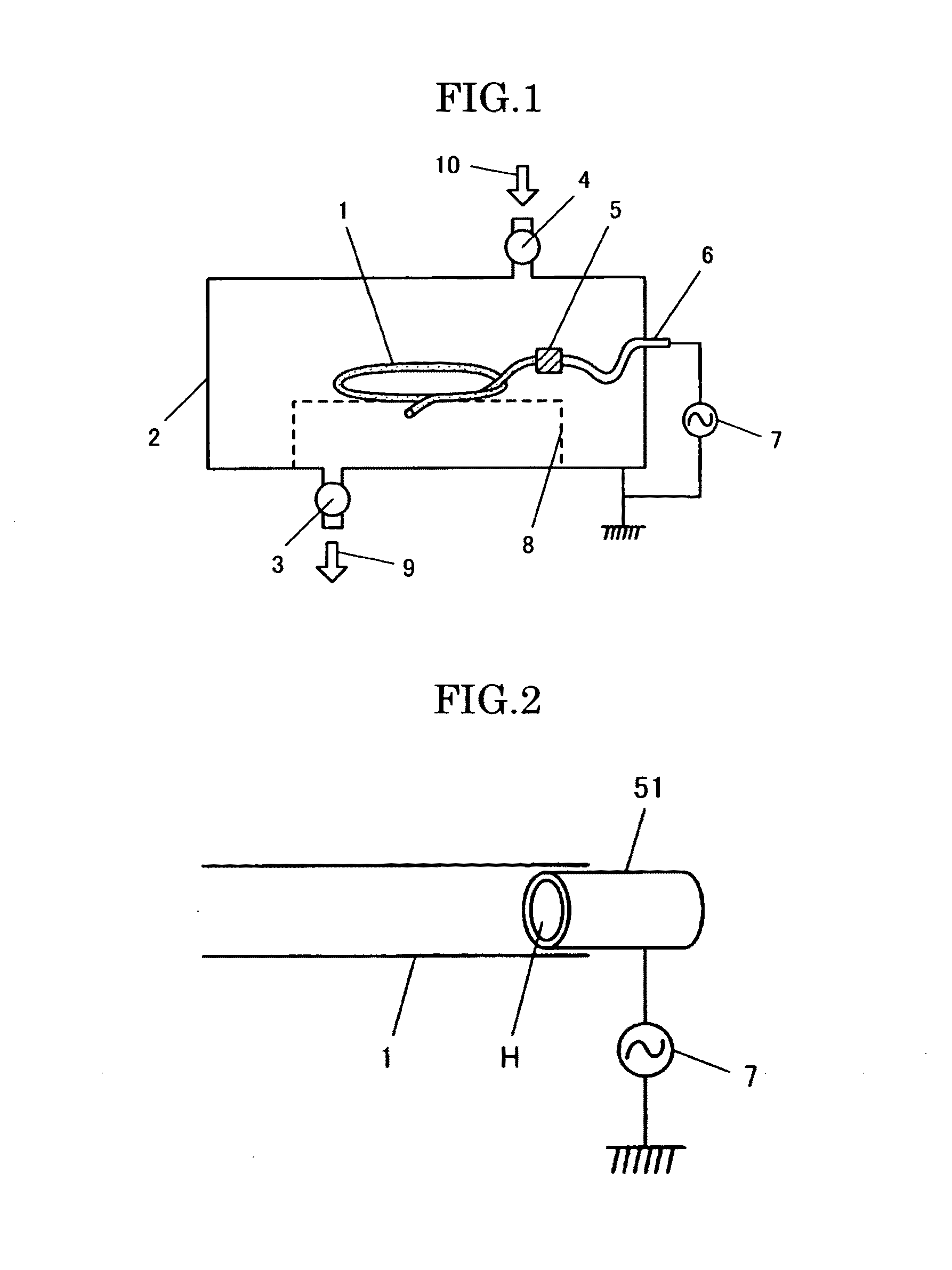
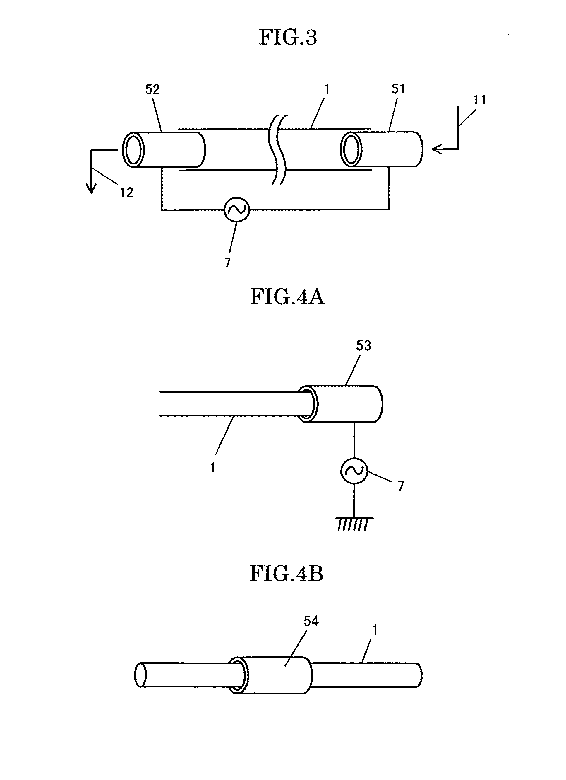
[0103]Long tubules to be sterilized (made of silicon rubber) having an inner diameter of 2 mm and 4 mm and a length of 50 cm were used, and experiments were carried out in the plasma sterilizing device in FIG. 1.

[0104]An electrode 5 was provided only at one end of the long tubule, and the cylindrical container 2 (made of stainless steel and having an inner diameter of 200 mm and a length of 500 mm) was used as a grounding electrode.

[0105]An oxygen gas was introduced into the container 2 and the pressure within the container 2 (outside the long tubule 1) was set within a range of 200 Pa to 340 Pa.

[0106]Next, an alternating current voltage of 4 kV to 6 kV having a frequency of 10 kHz and a pulse frequency of 10 pps was applied to the electrode 5, as shown in FIG. 6.

[0107]At this time, glow discharge could be confirmed only inside the long tubule. FIG. 9 shows the glow discharge generated inside the long tubule having an inner diameter of 2 mm. It is clear from the figure that plasma w...


PUM

PropertyMeasurementUnit
pressureaaaaaaaaaa
frequencyaaaaaaaaaa
lengthaaaaaaaaaa

Abstract

A plasma sterilizing device has a container for a long tubule to be sterilized, having an adjustable internal pressure, and an electrode provided at at least one end of the long tubule. The device is configured so that plasma is generated inside the long tubule by applying an alternating current voltage to the electrode in such a state that the pressure inside and outside of the long tubule can be adjusted, so that there is a predetermined difference in pressure between the inside and the outside of the long tubule.

Description

TECHNICAL FIELD[0001]This invention relates to a plasma sterilizing device and method, and in particular, to a plasma sterilizing device and method for carrying out a sterilizing process on a long tubule to be sterilized using plasma.BACKGROUND TECHNOLOGY[0002]Though according to some conventional methods for sterilizing long tubules, such as catheters and endoscopes, ultraviolet rays or high pressure steam is used, the efficiency of sterilization is low, and in some cases the material changes in quality due to the ultraviolet rays or heat. Though other conventional methods using ethylene oxide gas, liquid hydrogen peroxide and steam are highly effective, ethylene oxide and hydrogen peroxide are poisonous, and hydrogen peroxide can be harmful to the handler if it gets on the clothes. In addition, liquids and gases do not reach deep inside the long tubule, due to their viscosity, in accordance with methods other than those using ethylene oxide, and ultraviolet rays are insufficiently...

Claims


Application Information

Patent Timeline
Patent Type & Authority Patents(United States)
IPC IPC(8): H05H1/00A01N1/02A61L2/00A61L9/00B01J19/08
CPCA61L2202/24H05H1/0081A61L9/00A61L2/14A61L2/00A01N1/0294
Inventor HAYASHI, NOBUYAKITAZAKI, SATOSHI
Owner SAGA UNIVERSITY
Why Eureka
Try Eureka