

Separator for electrochemical cell and method for its manufacture
a technology of electrochemical cells and separator membranes, which is applied in the field of electrochemical cells, can solve the problems of affecting the performance of batteries, affecting the cycle life and power, and presently used separator membranes, and achieves the effects of low cost and function, excellent adhesion to electrodes, and high performan
- Summary
- Abstract
- Description
- Claims
- Application Information
AI Technical Summary
Benefits of technology
Problems solved by technology
Method used
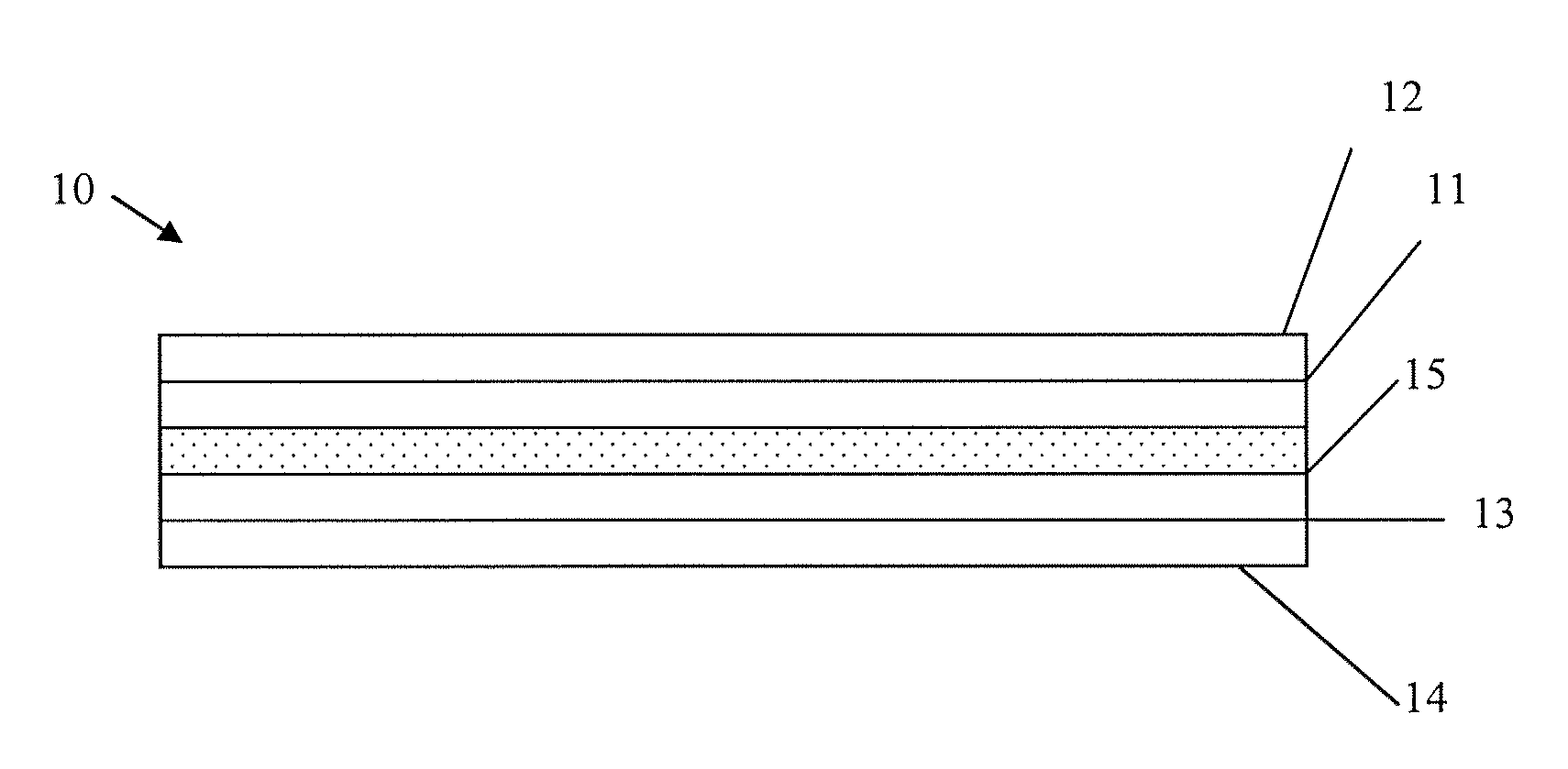
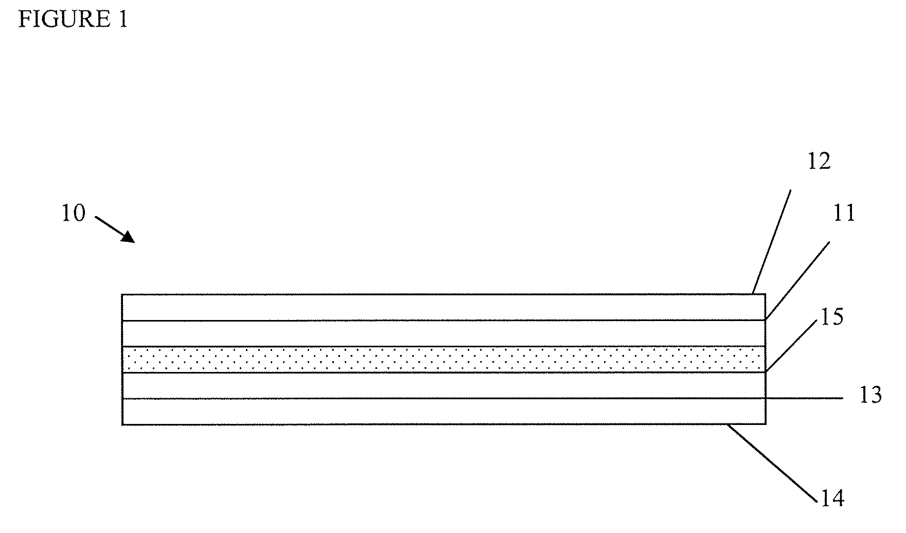
Image

Examples
example 1
Preparation of a Porous Separator
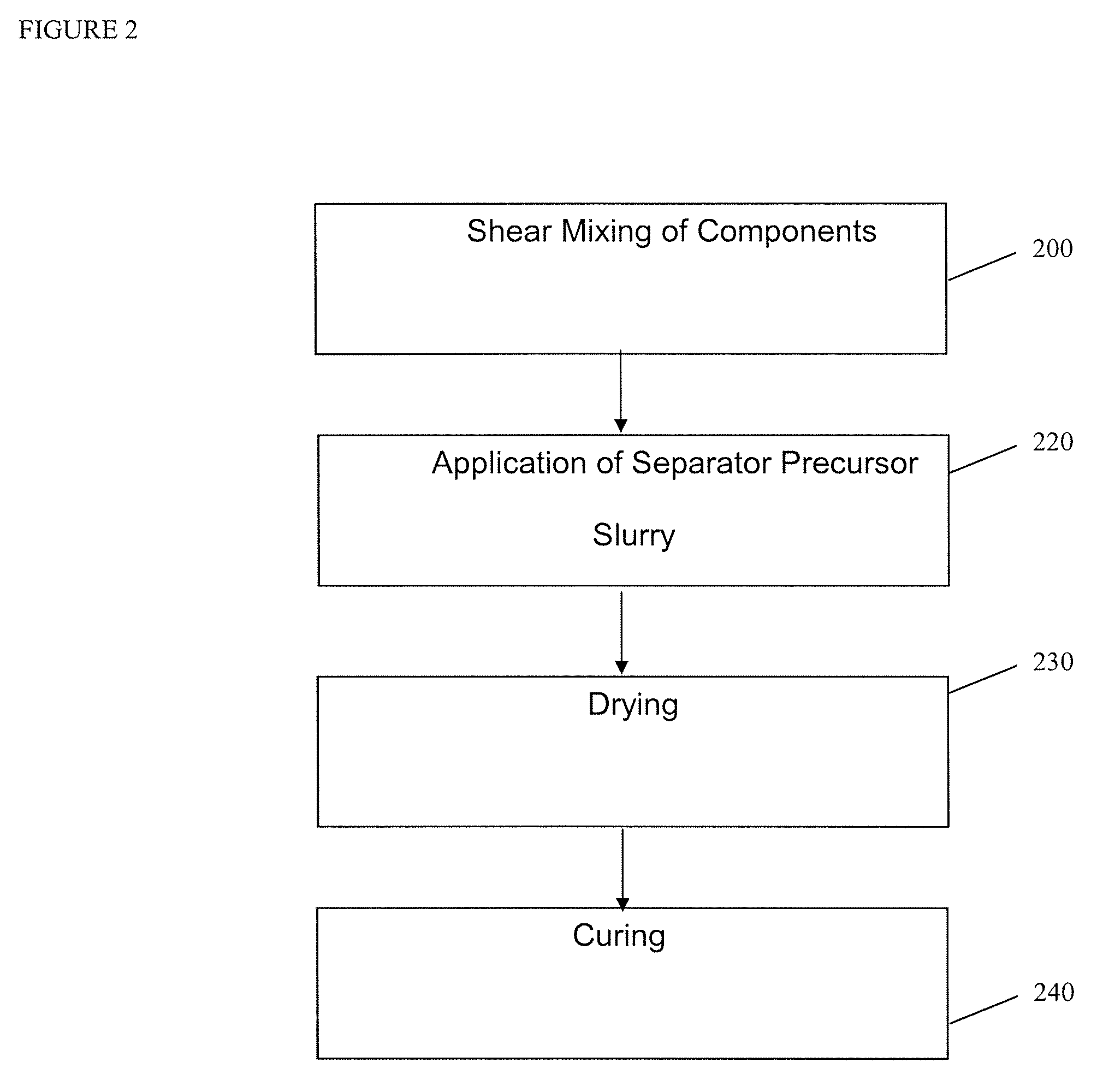
[0121]Membranes for lithium-ion cells were prepared from a 65:35 mixture of fumed silica and PVDF. Membranes were prepared from Kureha 7208 PVDF NMP solution and fumed silica with a surface area of approximately 200 m2 / g. The ratio of silica to polymer was 65:35 on a weight basis, and a 7% loading of these solids was slurried in a 30:70 (volume / volume) mixture of NMP and acetone. This slurry was prepared by first thoroughly mixing the silica into the PVDF / NMP solution using an orbital mixer at a low speed until highly dispersed, and then slowly adding the acetone to this dispersion mixing first at low speed and then at very high speeds until a stable suspension is formed. This is then loaded into a HVLP spray gun.
[0122]This coating composition was applied to either a body of anode or cathode material intended for use in a lithium-ion cell. The dry thickness of the application was approximately 20 microns and it was applied in 3 to 5 separate coats, w...
example 2
Measurement of Leakage Current
[0125]Leakage current is a figure of merit in predicting cell shelf-life.
[0126]A porous membrane prepared substantially as described in Example 1 was prepared with the following modifications. The silica separator was laid down in either one or two passes onto a lithium iron phosphate based cathode. In the former, the process protocol is to spray, dry, and then cure the layer. If the latter, then the protocol is to follow the spray / dry / spray / dry / cure technique.
[0127]Cells were prepared with Li metal anodes in a single layer pouch format by placing the coated cathode made of a lithium iron phosphate material (LFP) directly adjacent to a counter electrode of Li metal in a pouch container that is sealed on three sides, filling the cell with electrolyte and then sealing the fourth side so that the interior is totally isolated from the external environment. The cells were cycled three times (+C / 2, −C / 5) before being charged to 3.0V and left at open circuit. ...
example 3
Evaluation of Cell Life Cycle
[0129]Cell power is an important figure of merit. The impact of separator choice on cell power is estimated by comparing cells which are the same with exception of separator—this has been done using a pouch cell including a cathode comprising a lithium iron phosphate containing electroactive material (“M1”) and an anode comprising a lithium titanate (“LTO”).
[0130]A porous membrane prepared substantially as described in Example 1 was prepared with the following modifications. The silica separator was prepared as follows. electrodes (2 cm×2 cm) of M1 and LTO were each coated with about 2-5 coats of silica separator as previously described. These electrodes were then placed in a polymeric pouch, flooded with mixed carbonate / LiPF6 electrolyte appropriate for a lithium ion battery and sealed to the outside environment. Similarly, 2 cm×2 cm electrodes of LTO and MI were prepared and sealed into a similar pouch separated by a polyolefin membrane. In all respect...
PUM
| Property | Measurement | Unit |
|---|---|---|
| thickness | aaaaa | aaaaa |
| thickness | aaaaa | aaaaa |
| particle size | aaaaa | aaaaa |
Abstract
Description
Claims
Application Information