
Indoor surveying apparatus

a surveying apparatus and indoor technology, applied in the field of surveying equipment, can solve the problems of surveyors having to spend a considerable amount of time on-site taking measurements, data they capture, and very slow workflow using such tools

Active Publication Date: 2014-04-15
PLANITAR INC
View PDF4 Cites 49 Cited by
  • Summary
  • Abstract
  • Description
  • Claims
  • Application Information

AI Technical Summary

Benefits of technology

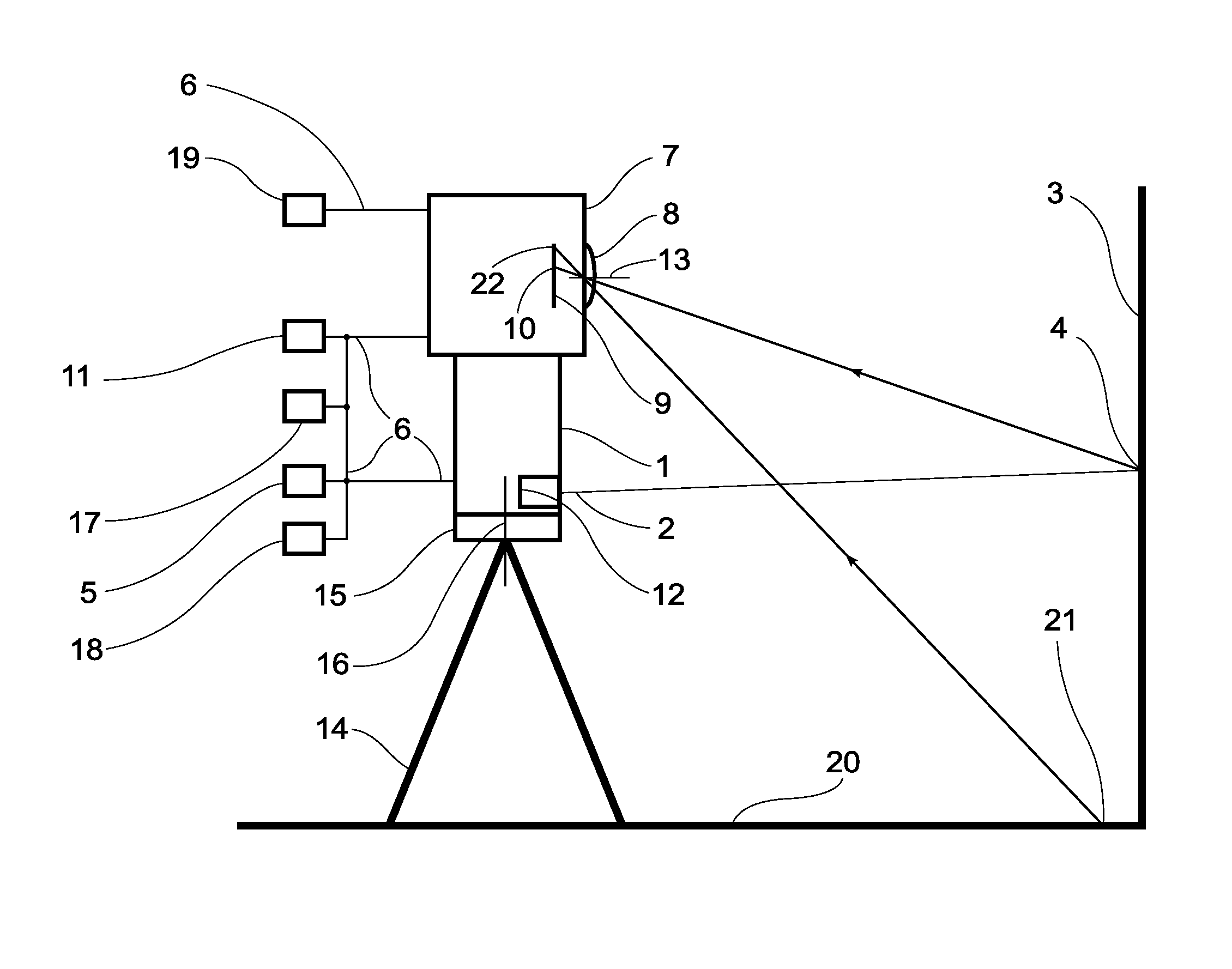
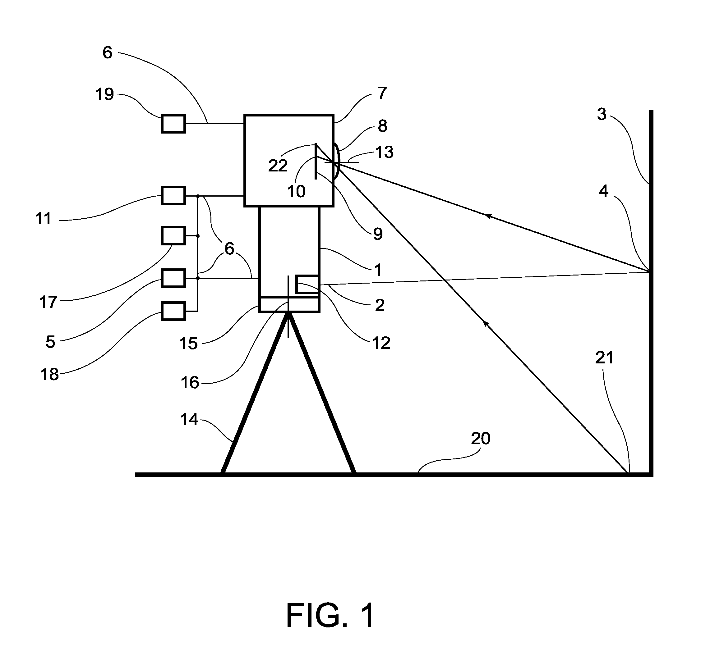
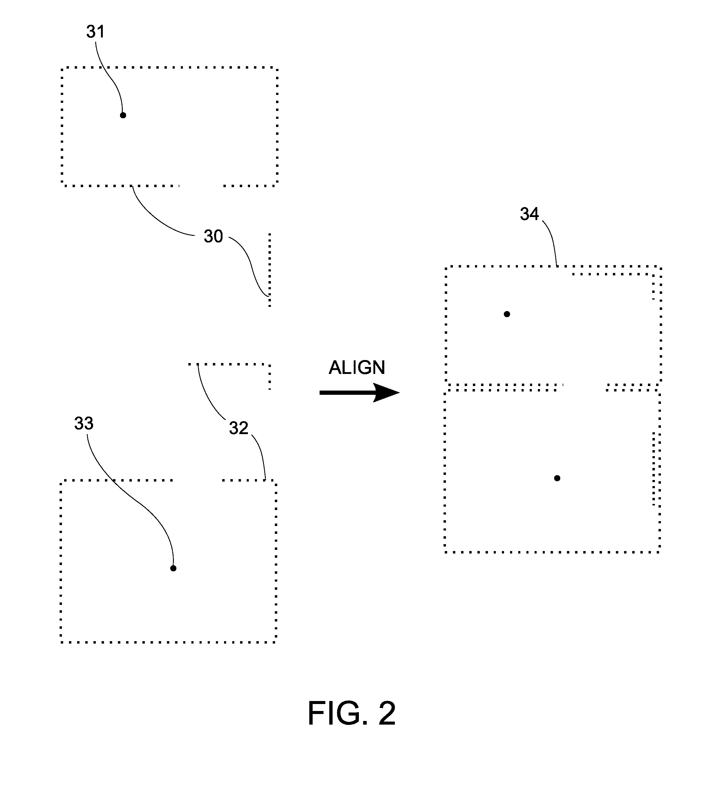
The present invention is an indoor surveying apparatus that can automatically construct a map of an indoor environment using measured 2D data sets. It includes a 2D range finder, like a scanning laser range finder or a triangulation laser range finger, to measure points in the environment. An optical imaging system with a panoramic lens and a rotator can capture images and align the 2D data sets to create a floor plan. The apparatus also includes a computing device to process the constructed map and image data to create floor plans and images correlated with the floor plan. The apparatus allows for accurate surveying of indoor spaces and helps to establish positions and extents of walls, doors, and windows, as well as draw floor plans where the map information is missing.

Problems solved by technology

Nevertheless, a workflow using such tools is very slow and a surveyor needs to spend a considerable amount of time on-site taking measurements.
While such instruments are versatile, the amount of data they capture is excessive for the usage scenarios listed above, the time required to capture a 3D scan of a room is still on the order of few minutes, and the cost of such instruments is prohibitively expensive for the mentioned uses.
Furthermore, where a definition or use of a term in a reference, which is incorporated by reference herein is inconsistent or contrary to the definition of that term provided herein, the definition of that term provided herein applies and the definition of that term in the reference does not apply.
Since the robots described above are not designed for the indoor surveying usage scenarios such as those listed earlier, their use for such purposes would be complicated for an average user and too time-consuming.
In addition, they do not provide means for drawing floor plans and creating virtual tours.

Method used


Image

  • Indoor surveying apparatus
  • Indoor surveying apparatus
  • Indoor surveying apparatus

Examples


Embodiment Construction

[0014]Features and advantages of the present invention will be better understood by reading the following detailed description, taken together with the drawing.

[0015]Before the present invention is described in further detail, it is to be understood that the invention is not limited to the particular embodiments described, as such may, of course, vary. It is also to be understood that the terminology used herein is for the purpose of describing particular embodiments only, and is not intended to be limiting, since the scope of the present invention will be limited only by the appended claims. Unless defined otherwise, all technical and scientific terms used herein have the same meaning as commonly understood by one of ordinary skill in the art to which this invention belongs. Although any methods and materials similar or equivalent to those described herein can also be used in the practice or testing of the present invention, a limited number of the exemplary methods and materials a...


PUM


Abstract

An indoor surveying apparatus comprises a 2D range finder, means for automatically aligning 2D range finder data and computing a 2D map of the environment, a calibrated optical imaging system for capturing images of environment, and means for establishing positions and extents of walls, doors, and windows and for drawing floor plans using the computed 2D map and calibrated images where 2D range finder data is missing. It is further contemplated that the imaging system can also be part of the range finder, that the range finder can be a scanning laser range finder, that the imaging system can include a panoramic lens with 180 degree field of view, that the apparatus can further include an IMU, an electronic compass, a panoramic rotator, and means for measuring positions of points on the floor using the image data.

Description

BACKGROUND OF THE INVENTION[0001]The field of the present invention is surveying apparatuses for measuring layout of buildings. A surveying apparatus necessarily performs a geometric instrument function and, depending on the underlying technology, can perform an optical measuring function.[0002]Currently, buildings are surveyed most of the time using simple measuring tools, such as a mechanical tape measure or a lasertape measure”—a laser distance meter. U.S. Pat. No. 7,640,214 and U.S. patent application Ser. No. 10 / 724,259 describe systems that add angle measuring capabilities to laser distance meters to increase speed and efficiency with which the measurements can be done. Nevertheless, a workflow using such tools is very slow and a surveyor needs to spend a considerable amount of time on-site taking measurements.[0003]It would be advantageous to be able to capture surveying data on-site quickly and to allow post-processing and analysis of data and creation of floor plans to be...

Claims


Application Information

Patent Timeline
Patent Type & Authority Patents(United States)
IPC IPC(8): G01C3/08
CPCG01C15/002G01C3/08G01S17/42G01S17/89G01C15/02G01S7/4817G01S17/48G06F17/5004
Inventor LIKHOLYOT, ALEXANDER
Owner PLANITAR INC
Learn More