System for a single point plug-in, connection of any combination of electric energy supply sources combined with smart load management and control of both supply and consumption of electric energy by a home or small business

a single point plug-in and electric energy supply technology, applied in the direction of process and machine control, electrical equipment casings/cabinets/drawers, instruments, etc., can solve the problems of limiting the cost effective development of alternative renewable sources of electric generation, affecting the safety of connection, and requiring more effort or energy to get a train car from a dead stop. , to achieve the effect of eliminating costly and disruptive rewiring of the home and allowing the safe connection

Active Publication Date: 2014-04-15
NATUS ENERGY
View PDF5 Cites 42 Cited by
  • Summary
  • Abstract
  • Description
  • Claims
  • Application Information

AI Technical Summary

Benefits of technology

[0016]It would be advantageous to provide a plug-in, single point connection on the exterior of the Home or Small Business that would effectively permit the safe connection of any type of electrical supply source to the Home or Small Business eliminating costly and disruptive rewiring of the Home or Small Business's electrical service entrance and or the Main Service Panel.
[0017]It would further be advantageous to provide a system that can be monitored and managed though the Internet by the owner or local serving Electric Power Utility Company or both wherein both GTC operational and environmental site parameters at the Home or Small Business could be observed.
[0018]It would further be advantageous to provide a system that provides for wireless, near real time, automated smart energy conservation control and management down to an individual participating Electric Appliance level inside the Home or Small Business that functions by applying pre-programmed rules based triggers in response to receiving real time market pricing signals from the local serving Electric Power Utility Company through IP Networked Communication.

Problems solved by technology

As demand for electric energy has increased the Utility Power Grid is often operating at full transmission capacity and not capable of transmitting larger amounts of electricity at given moments in time.
Beyond overcoming the environmental limitations, having sufficient transmission capacity in the Grid limits the cost effective development of alternative renewable sources of electric generation.
So significant in fact, Electric Power Utility Companies are worried what impact these independently owned and operated, Grid connected, MDRG sites will have on the overall Grid stability, especially when the Electric Power Utilities have little or no control over the operation of these thousands or millions of MDRG sites.
Getting a train car rolling from a dead stop requires more effort or energy than keeping it rolling.
While this Peak Load or Surge Current only lasts for a moment, it can result in elevating the overall cost of electricity provided by the local serving Electric Power Utility Company because they must be ready and able to meet these Peak Demands and have standby generation sources up and running to do so.
There have been and are times when Peak Loads become so large, that even with standby generation Electric Power Utility Companies cannot supply the additional electricity and the result is what is called a “Brown Out” or where supply is not sufficient to meet the Peak Demand.
What has not been addressed and is not becoming more affordable are the labor costs associated with installing MDRG and IMDLM.
Most of this cost is the, time consuming wiring, involved with connection to the Main Service Panel of the Home or Small Business.
While new construction offers simplified access for wiring, the labor is still significant and there historically has been very little standardization to the installation and wiring process for MDRG on Homes and Small Businesses.
Existing Homes and Small Businesses interject a multitude of additional complexities that all add labor costs to the installation process.
Most MDRG and IMDLM systems for residential or small business applications are not designed to support more than a small number of isolated circuits in the Home or Small business.
Most do not support any type of IP Networked Communication for remote monitoring and automated diagnostic reporting of Operating Parameters across the Internet for the Smart Load Management.
There is no integrated functionality for controlling electric load and generation resources.

Method used


Image

  • System for a single point plug-in, connection of any combination of electric energy supply sources combined with smart load management and control of both supply and consumption of electric energy by a home or small business
  • System for a single point plug-in, connection of any combination of electric energy supply sources combined with smart load management and control of both supply and consumption of electric energy by a home or small business
  • System for a single point plug-in, connection of any combination of electric energy supply sources combined with smart load management and control of both supply and consumption of electric energy by a home or small business

Examples


Embodiment Construction

[0035]Before explaining the disclosed embodiment of the present invention in detail it is to be understood that the invention is not limited in its application to the details of the particular arrangement shown since the invention is capable of other embodiments. Also, the terminology used herein is for the purpose of description and not of limitation.

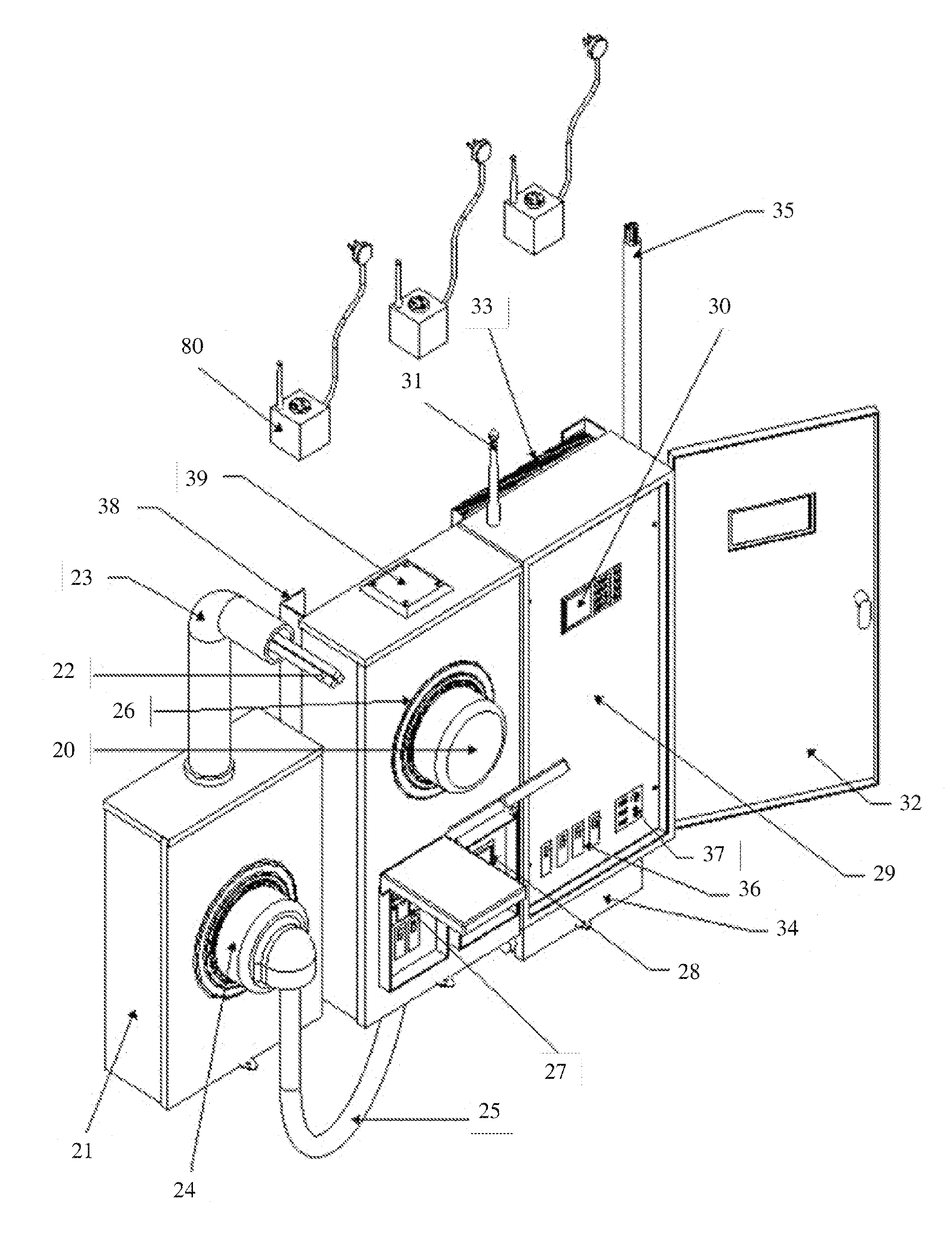
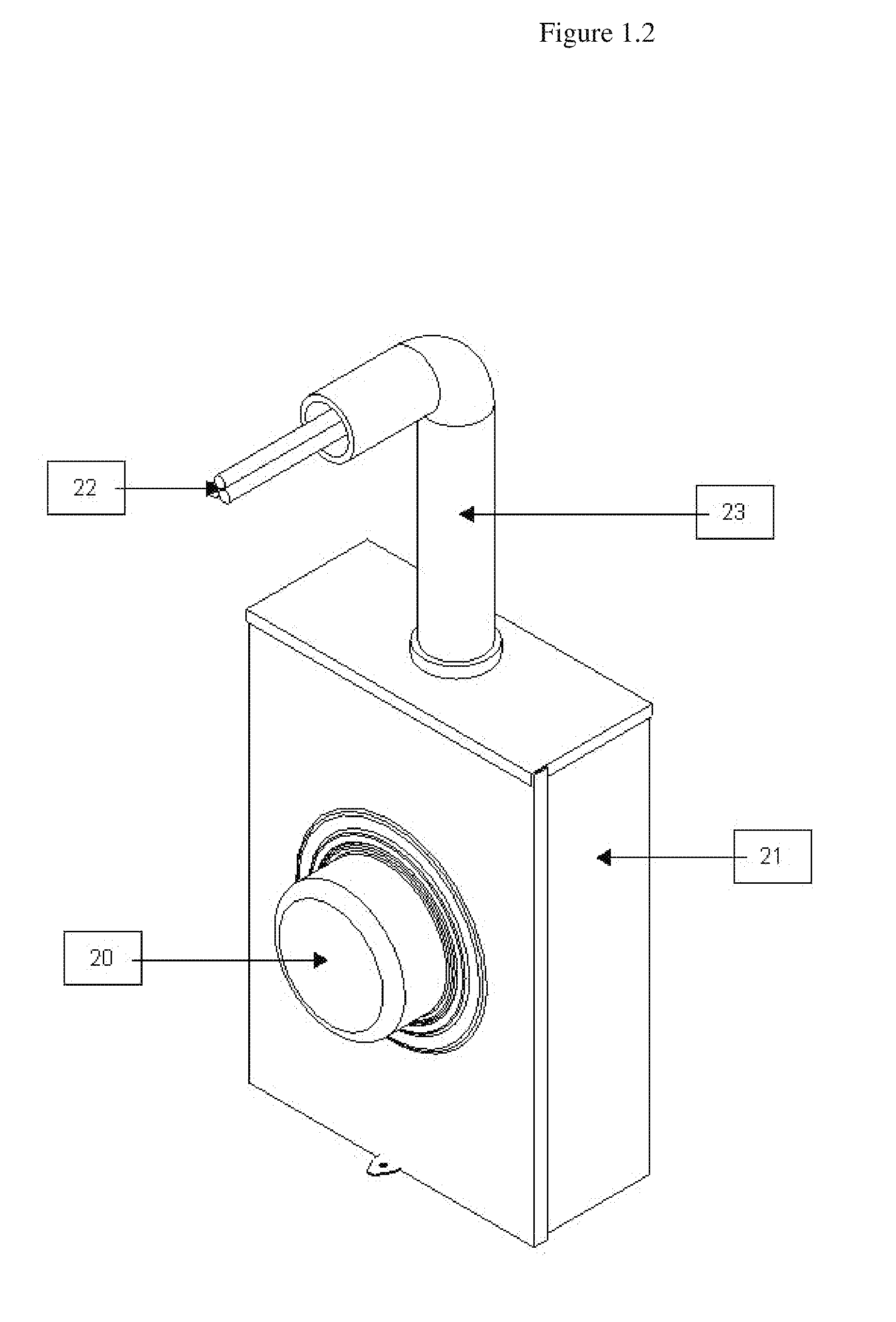
[0036]FIG. 1.2 is a typical perspective view of the Meter Receiver Box (21) and the Electric Meter (20) with the Power Mast (23), used on most residential and small business buildings. This is considered a typical installation on most Homes and Small Business buildings in the United States. This embodiment includes a set of Feed In Utility Power Lines (22) coming from the Utility Power Grid; The Feed In Utility Power Lines are attached to the Meter Receiver Box (21) through the Power Mast that is connected either from overhead or coming up from underground. The Electric Meter is plugged into the Meter Receiver Box thus completing the c...


PUM


Abstract

A standardized system, method and apparatus for connection of any combination of electric energy supply source including the Utility Power Grid, Auxiliary Generator, Wind Turbine, Fuel Cell, Storage Battery, Solar Panel Array, and an Electric Car which are collectively aggregated to feed into the main Service Panel of the Home or Small Business through a single plug-in connection to the Home or Small Business's electrical service entrance and provide for collective operational monitoring and management through an IP Networked Communication Link, commonly referred to as IP Networked Communication across the Internet, thereby providing bidirectional communication and control between the GTC and the Smart Load Management functionality resident on the Internet Cloud.

Description

FIELD OF THE INVENTION[0001]The present invention synergistically relates to the distributed renewable alternative energy and home energy management industries. More particularly to, a system, method and apparatus for lowering the cost of installation by standardizing the process, accomplishing it completely outside the Home or Small Business and better controlling both the generation and use of electric energy by the Home or Small Business. The present invention further relates to a method of not only controlling the overall utilization of electric energy in the Home or Small Business as stated above, but also the monitoring and control of a Peak Demand or also called a Peak Load for the use of electric energy at any given moment in time. Management of Peak Demands or Loads is referred to as Demand Response Management by an Electrical Power Utility Companies. The condition of excessive Peak Demand often require the Electric Power Utility Companies to Load Shave or reduce overall el...

Claims


Application Information

Patent Timeline
Patent Type & Authority Patents(United States)
IPC IPC(8): H05K5/00G05D7/00
CPCY02B10/14Y02E10/58Y04S10/126Y02E10/763H02J3/387H02J3/14H02J3/386H02J3/385H02J3/381Y02B10/30Y02E60/721Y10T307/724H02J2300/40H02J2300/30H02J2300/28H02J2300/26Y02A30/60Y02B10/10Y02E10/56Y02E10/76H02J2310/60H02J3/388Y02E60/00
Inventor MATHIOWETZ, MICHAEL
Owner NATUS ENERGY
Why Eureka
Try Eureka