Supercharge Your Innovation With Domain-Expert AI Agents!

LED current control in a dimmable LED illumination system

a technology of led current control and dimmable light, which is applied in the direction of electric variable regulation, process and machine control, instruments, etc., can solve the problems of consuming power, consuming power, and being unable to properly use the leds to couple the leds with the electronic transformers

Active Publication Date: 2014-04-22
MAXIM INTEGRATED PROD INC
View PDF10 Cites 8 Cited by
  • Summary
  • Abstract
  • Description
  • Claims
  • Application Information

AI Technical Summary

Benefits of technology

Enables the dimmable LED illumination system to maintain operation with electronic transformers by regulating the LED current based on the boost voltage, ensuring consistent brightness levels and preventing transformer startup issues.

Problems solved by technology

When compared to halogen lamps, LEDs are relatively smaller, and have a longer operating life.
Although customers would like to replace the halogen lamp with LEDs, the original illumination system may not be compatible to the LEDs or properly used to couple the LEDs with the electronic transformers.
A single LED lamp consumes a power in the range of 5-10 watts, and when it is loaded to the conventional halogen illumination system, it is inadequate to keep the electronic transformer operational.
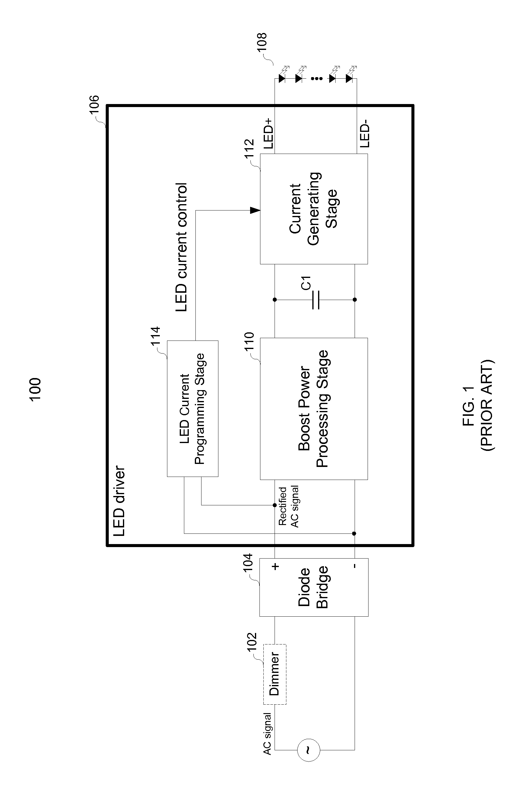
Although it functions properly when the ac signal is directly provided from the wall output, the dimmable illumination system 100 fails when an electronic transformer is applied to convert the ac signal to a lower-voltage ac signal.

Method used


Image

  • LED current control in a dimmable LED illumination system
  • LED current control in a dimmable LED illumination system
  • LED current control in a dimmable LED illumination system

Examples


Embodiment Construction

[0024]In the following description, for the purpose of explanation, specific details are set forth in order to provide an understanding of the invention. It will be apparent, however, to one skilled in the art that the invention can be practiced without these details. One skilled in the art will recognize that embodiments of the present invention, described below, may be performed in a variety of ways and using a variety of means. Those skilled in the art will also recognize additional modifications, applications, and embodiments are within the scope thereof, as are additional fields in which the invention may provide utility. Accordingly, the embodiments described below are illustrative of specific embodiments of the invention and are meant to avoid obscuring the invention.

[0025]Reference in the specification to “one embodiment” or “an embodiment” means that a particular feature, structure, characteristic, or function described in connection with the embodiment is included in at le...


PUM


Abstract

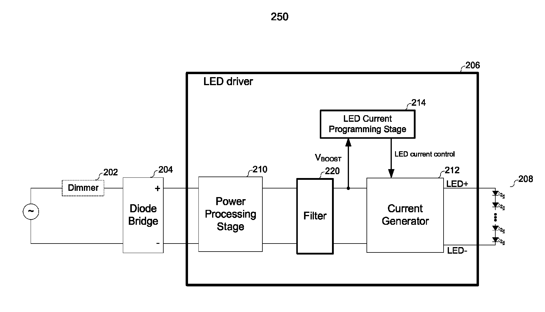
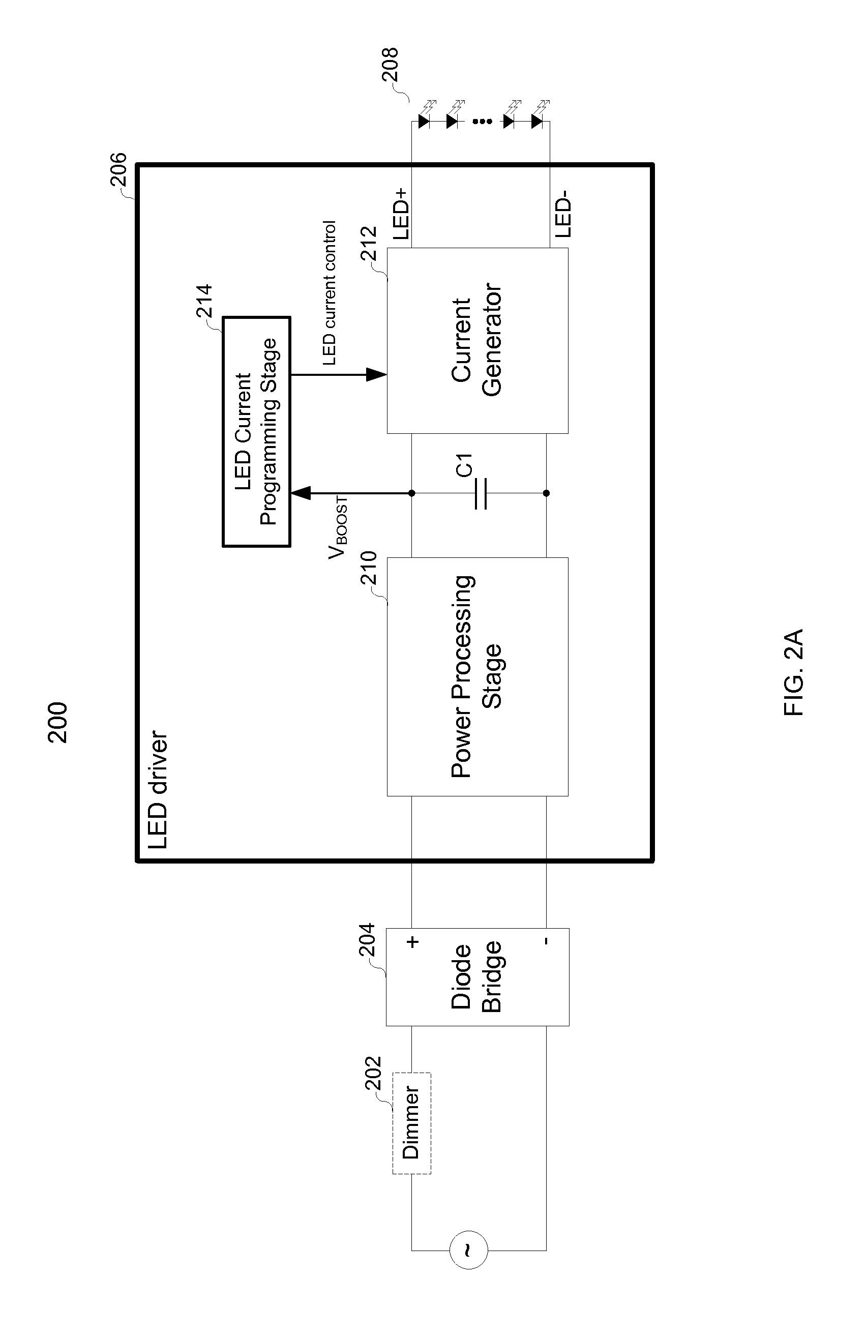
The invention relates to a light emitting diode (“LED”) illumination system, and more particularly, to systems, devices and methods of driving a LED module by a current generator that is powered and controlled by a regulated dc voltage associated with a brightness level. Such a dimmable LED illumination system is compatible with both a high-voltage ac signal coupled from any wall outlet and a low-voltage ac signal provided by an electronic transformer. A diode bridge rectifies the ac signal to a rectified ac signal, and a LED driver generates the LED current from the rectified ac signal and drives the LED to the brightness level. Within the LED driver, the level of the LED current is determined from a boost voltage that is substantially a regulated dc voltage generated from the rectified ac signal.

Description

CROSS REFERENCE TO RELATED APPLICATION[0001]The application claims the benefit under 35 U.S.C. §119(e) of Provisional Application Ser. No. 61 / 556,417, entitled “LED Current Control in a Dimmable LED Illumination System”, filed on Nov. 7, 2011, the subject matter of which is incorporated herein by reference.BACKGROUND[0002]A. Technical Field[0003]The present invention relates to a dimmable light emitting diode (hereinafter, “LED”) illumination system, and more particularly, to systems, devices and methods of driving a LED module by a current generator that is powered and controlled by a regulated dc voltage associated with a brightness level. Such a dimmable LED illumination system is compatible with both a high-voltage ac signal coupled from any wall outlet and a low-voltage ac signal provided by an electronic transformer.[0004]B. Background of the Invention[0005]Semiconductor-based solid-state lighting (SSL), until recently associated mainly with simple indicator lamps in electroni...

Claims


Application Information

Patent Timeline
Patent Type & Authority Patents(United States)
IPC IPC(8): H05B37/02H05B33/08H05B44/00
CPCH05B33/0833H05B33/086Y02B20/348H05B37/02Y02B20/30H05B47/10H05B45/38H05B45/375H05B45/30H05B45/3725H05B45/385H05B45/10
Inventor HARIHARAN, SURESH
Owner MAXIM INTEGRATED PROD INC
Features
  • R&D
  • Intellectual Property
  • Life Sciences
  • Materials
  • Tech Scout
  • Unparalleled Data Quality
  • Higher Quality Content
  • 60% Fewer Hallucinations
Learn More