Method and device for processing 3-D image data of a skull

a 3-d image and data processing technology, applied in the field of 3d image data processing of skulls, can solve the problem of time-consuming diagnosis and achieve the effect of improving fracture presentation and short tim

Active Publication Date: 2014-04-22
SIEMENS HEALTHCARE GMBH +1
View PDF8 Cites 2 Cited by
  • Summary
  • Abstract
  • Description
  • Claims
  • Application Information

AI Technical Summary

Benefits of technology

The invention is a method to create a 3D image of a skull that can be quickly overviewed in 2D using a film sequence. The method involves determining image data at different distances from the skull surface, which can be presented in chronological order. This allows clinical personnel to quickly understand the situation of the skull in different depths from the surface. The method is particularly useful for fracture presentations, where image data is determined at a distance of 0 to 5 mm from the skull surface, specifically the region of the tabula externa.

Problems solved by technology

The technical problem addressed in this patent is to create a method and device for processing the 3D image data of a skull that allows a fast diagnosis by the attending physician or diagnosing person, while reducing the required computation and cost expenditures as low as possible. The method should allow for a 2D overview presentation of certain parts of the skull, which can help in identifying fractures and other pathological structures in a faster and more efficient way.

Method used


Image

  • Method and device for processing 3-D image data of a skull
  • Method and device for processing 3-D image data of a skull
  • Method and device for processing 3-D image data of a skull

Examples


Embodiment Construction

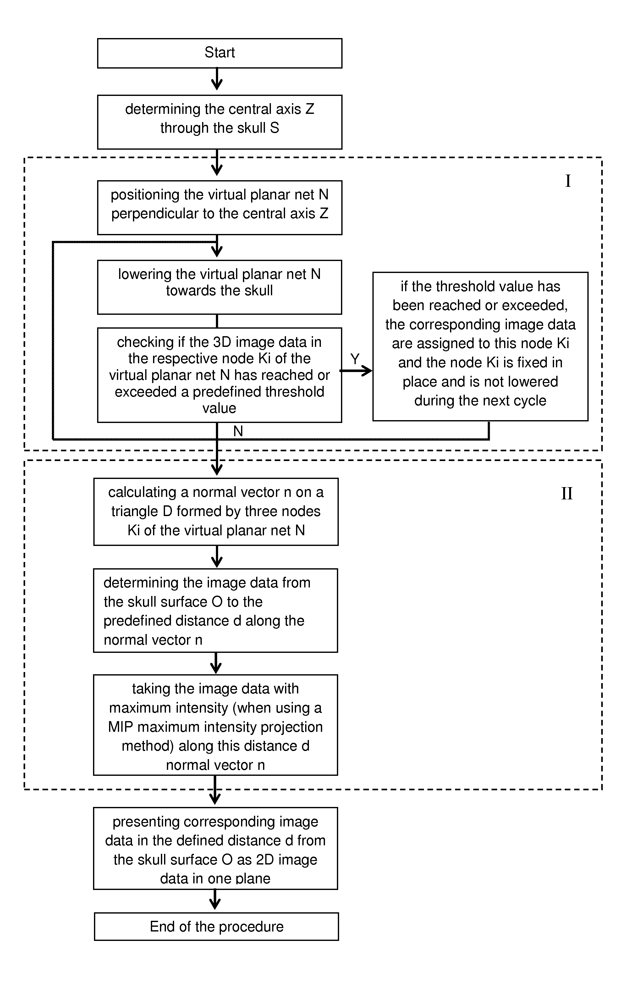
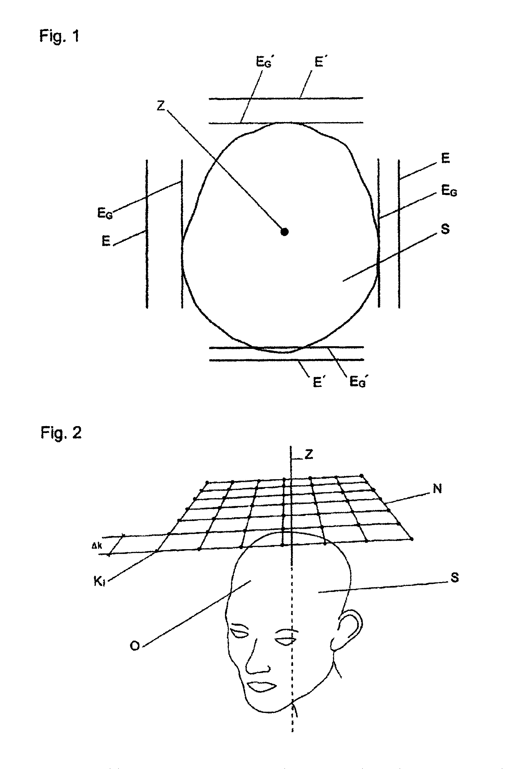
[0049]FIG. 1 shows an image of a human skull S viewed from above which was taken, for example, with a computer tomograph. The presentation method is, for example, a maximum intensity projection of all CT images of the skull S, wherein substantially only the bony structure is visible. For determining a central axis Z through the skull S, two pairs of parallel virtual planes E, E′ preferably arranged at right angles to each other are formed, and the planes E, E′ of each pair are moved from a position on both sides of the skull S toward each other. As soon as the 3D image data of the skull S reach or exceed a predefined threshold value, for example a predefined density value in Hounsfield units (HU), the planes E and E′ come to a standstill as so-called boundary planes EG and EG′, respectively. Finally, the skull S is quasi clamped between the parallel boundary planes EG and EG′. The section axis of the center planes arranged between the parallel boundary planes EG, EG′ is now defined ...


PUM


Abstract

The invention relates to a method and a device for processing 3-D image date of a skull (S), wherein image date are selected or calculated for the 3-D image data and are presented as 2-D image data in a plane. For fast, overview-like inspection of the skull (S), the skull surface (O) is determined from the 3-D image data, and the corresponding image data at a defined distance (d) from the skull surface (O) are determined and presented as 2-D image data in a plane.

Description


Claims


Application Information

Patent Timeline
Owner SIEMENS HEALTHCARE GMBH
Why Eureka
Try Eureka