Flight recorder deployment system and method

a deployment system and flight recorder technology, applied in the field of flight recorder deployment system and method, can solve the problems of flight recorder only being useful to investigators, flight recorder not being able to be located on downed aircraft, flight recorder not being able to survive, etc., to reduce the likelihood of non-commanded or unintended deployment and high reliability of deployment

Active Publication Date: 2014-04-22
DRS C3 & AVIATION
View PDF17 Cites 30 Cited by
  • Summary
  • Abstract
  • Description
  • Claims
  • Application Information

AI Technical Summary

Benefits of technology

[0006]Embodiments of the invention are directed to automatic deployable flight data recorder systems and methods for automatically initiating deployment of a flight recorder from an aircraft. Embodiments of the invention provide a more robust crash detection system that reduces the likelihood of non-commanded or unintended deployment of a flight recorder from an aircraft while maintaining a high reliability of deployment in a catastrophic crash event.

Problems solved by technology

However, while a flight recorder is designed to survive a crash, there is still a probability that the flight recorder may not survive if the crash conditions are extreme enough.
Furthermore, a flight recorder is only useful for investigators if the flight recorder can be located after a crash.
For example, when an aircraft crashes at sea and is submerged in water, locating the flight recorder affixed to the downed aircraft can take weeks to months, and even years, and can be costly in terms of the amount of money and time spent in locating the flight recorder.
Even when an aircraft crashes on land, it may take significant effort and time to locate the flight recorder, for example, when the crash site is an unfamiliar or rough terrain.
Such delay in locating the flight recorder not only frustrates investigators but can also risk the safety of other aircrafts.
For example, when a catastrophic aviation event is caused by a design flaw in an aircraft component, the delay in identifying the problematic aircraft component can risk the safety of other aircrafts that employ the same type of aircraft component.
However, most deployable flight recorders are designed to deploy from the aircraft even at the slightest possibility of an aircraft crash, resulting in a high risk of false-positive crash detections.
This can cause non-commanded or unintended deployment of the flight recorder, and in some instances, has resulted in injuries to maintenance workers while the aircraft is being serviced on the ground.

Method used


Image

  • Flight recorder deployment system and method
  • Flight recorder deployment system and method
  • Flight recorder deployment system and method

Examples


Embodiment Construction

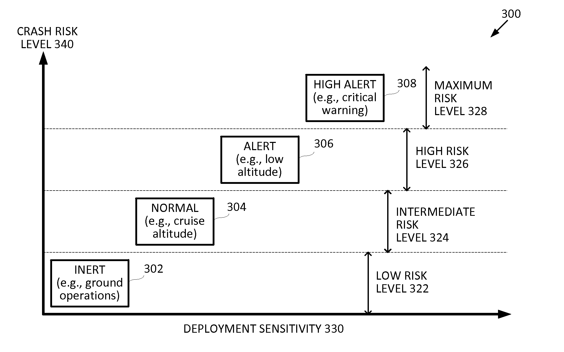
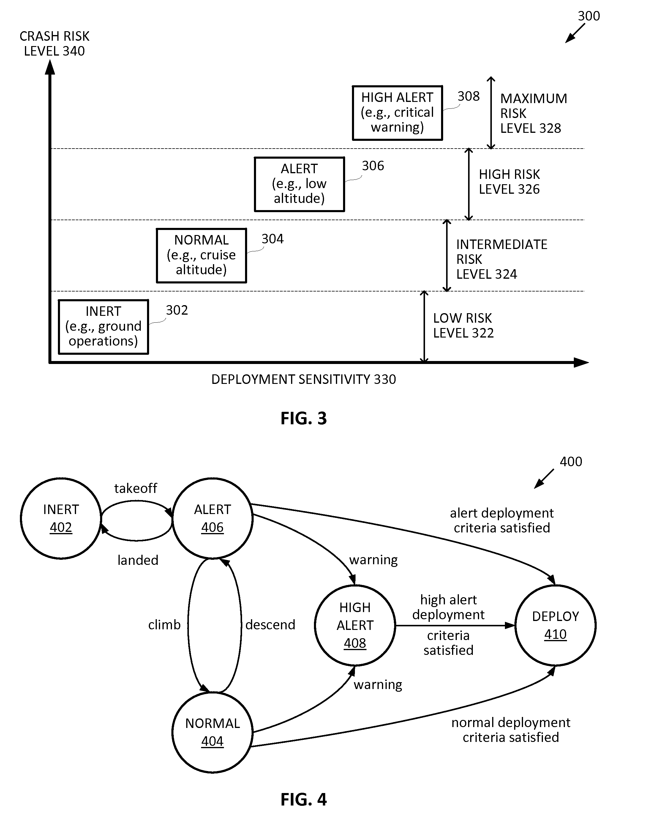
[0020]Embodiments of the present invention discloses improved automatic deployable flight recorder (ADFR) systems and methods to provide a more robust crash detection system that reduces the likelihood of non-commanded or unintended deployment of a flight recorder from an aircraft while maintaining a high reliability of deployment in a catastrophic crash event. Embodiments of the ADFR system utilizes sensor type and location diversity, sensor type flexibility and differentiation, sensor fault monitoring, components redundancy, and voting logic to improve the reliability of the ADFR system. Furthermore, the deployment criteria for deploying a flight recorder in embodiments of the invention can be adjusted based on the flight conditions of the aircraft and warning signals from aircraft warning systems to improve detection of a crash event and to reduce the possibility of false-positive triggers.

[0021]Exemplary ADFR Systems and Crash Sensors

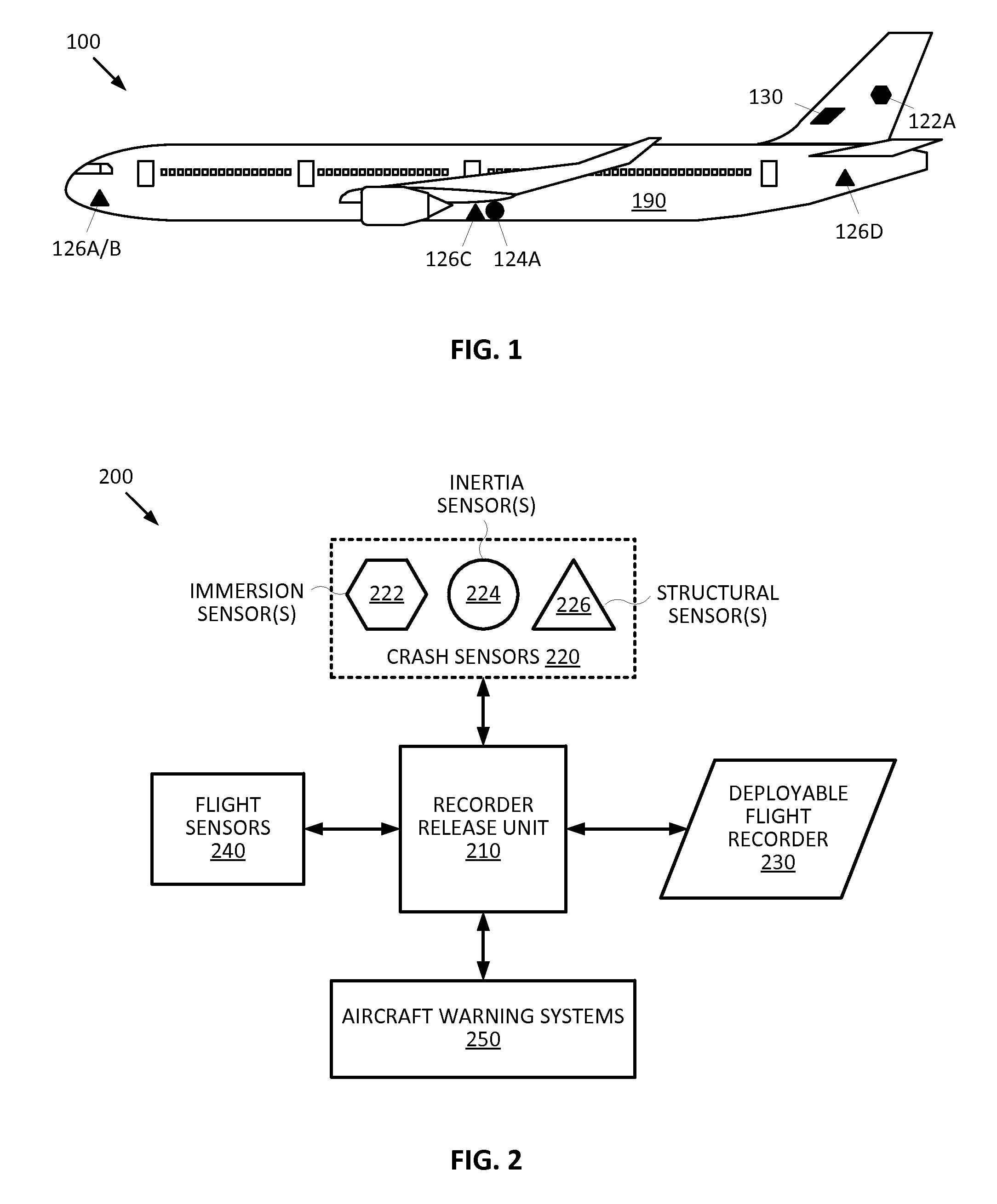
[0022]FIG. 1 illustrates an ADFR system 100 o...


PUM


Abstract

Embodiments of the invention provides an automatic deployable flight recorder (ADFR) system that includes a deployable fight recorder, a plurality of crash sensors, and a recorder release unit. The recorder release unit is communicatively coupled to the deployable fight recorder and the plurality of crash sensors, and is configured to initiate deployment of the deployable flight data recorder from an aircraft when a deployment criteria that is adjusted based on a flight condition of the aircraft is satisfied.

Description

CROSS-REFERENCES TO RELATED APPLICATIONS[0001]NOT APPLICABLEBACKGROUND[0002]In a catastrophic aviation event involving a downed aircraft, a flight recorder is one of the most useful tools for investigators to piece together the crucial moments leading up to the aircraft accident or incident to determine the cause of the crash. One type of flight recorder is a cockpit voice recorder (CVR) that records the audio environment of the flight deck of an aircraft. A CVR records conversations in the cockpit and communications between the cockpit crew and others such as air traffic control personnel on the ground. Another type of flight recorder is a flight data recorder (FDR) that records the status of and information about the electronic and mechanical equipment of the aircraft. A FDR records information such as flight parameters (e.g., altitude, speed, etc.) of the aircraft, and may include propulsion system information such as engine performance data, or other avionics information useful ...

Claims


Application Information

Patent Timeline
Patent Type & Authority Patents(United States)
IPC IPC(8): G06F19/00G06F7/00B60R22/32
CPCG07C5/085B64D45/00G06F7/00B64D2045/0065B60R22/32
Inventor VAN DEN HEUVEL, BLAKEKAUFMANN, ARIO'HARA, VINCENT JAMES
Owner DRS C3 & AVIATION
Why Eureka
Try Eureka