Gas filling system

a gas filling system and gas tank technology, applied in the direction of liquid handling, electrochemical generators, packaging goods types, etc., can solve the problems of high temperature in the gas tank, inability to complete specified amounts of gas, long filling time, etc., and achieve the effect of easy transmission of the filling protocol

Active Publication Date: 2014-04-29
TOYOTA JIDOSHA KK
View PDF36 Cites 21 Cited by
  • Summary
  • Abstract
  • Description
  • Claims
  • Application Information

AI Technical Summary

Benefits of technology

[0010]According to the invention, the vehicle-side controller has the filling protocol, so that it is possible to use the filling protocol determined in consideration of individual statuses on the vehicle side (characteristics of the gas tank, for example). When the filling protocol specific to each vehicle is used, it is possible to perform the filling adapted to the gas tank of the vehicle and it is therefore possible to complete filling a predetermined filling amount (the filling amount for a full tank or the amount of gas to be filled that is designated) of gas in a minimum period of time. In addition, it is necessary neither to prepare the filling protocol nor to renew the prepared filling protocol for each vehicle on the gas station side. Thus, it is made possible to perform the optimum filling operation for the future vehicles (gas tanks).
[0011]The vehicle may have a vehicle-side communication device connected to the vehicle-side controller and the gas station may include a station-side communication device that receives the filling protocol from the vehicle-side communication device and a station-side controller that is connected to the station-side communication device and controls the filling of the gas into the gas tank according to the filling protocol received. With this configuration, it is possible to establish a communication between the vehicle and the gas station and therefore, it is possible to easily transmit the filling protocol stored on the vehicle side to the gas station.
[0013]The dispenser may have a control valve that controls a flow rate of the gas supplied to the gas tank according to the filling protocol. With this configuration, the flow rate of the gas filled into the gas tank is easily controlled.
[0017]A configuration may be employed, in which the vehicle has a sensor that acquires information on the inside of the gas tank, the station-side communication device also receives, from the vehicle-side communication device, the information acquired by the sensor, and the station-side controller determines a filling flow rate according to the filling protocol received by the station-side communication, device and the information on the inside of the gas tank in performing control. With this configuration, it is possible to perform filling according to the state in the gas tank to be filled. In addition, because the information on the inside of the gas tank is acquired, it is possible to perform control of the filling flow rate more accurately as compared to the case where such information is estimated.
[0019]The sensor may include at least one of a temperature sensor and a pressure sensor. In this case, when it is detected that the temperature of the gas tank is high, for example, it is possible to restrict further increase in temperature in the gas tank by reducing the filling flow rate.

Problems solved by technology

Thus, there is a fear that the temperature in the gas tank quickly increases and reaches the design temperature (85° C., for example) and filling of a specified amount of gas cannot be completed.
On the other hand, when the filling flow rate is reduced, although the rapid increase in temperature is suppressed, the filling time becomes long.
In JP-A-2004-828211, however, filling is performed without taking the characteristics of the gas tank into consideration and therefore, filling is not improved with the improvement of the characteristics of the gas tank at present and in the future.

Method used


Image

  • Gas filling system
  • Gas filling system
  • Gas filling system

Examples


Embodiment Construction

[0028]Gas filling systems according to example embodiments of the invention will be described below with reference to the attached drawings. An example of the gas filling system will be herein described, in which hydrogen gas is filled from a gas station into a gas tank of a fuel cell vehicle equipped with a fuel cell system. As generally known, the fuel cell system includes a fuel cell that generates electricity through electrochemical reaction between fuel gas (hydrogen gas, for example) and oxidant gas (air, for example).

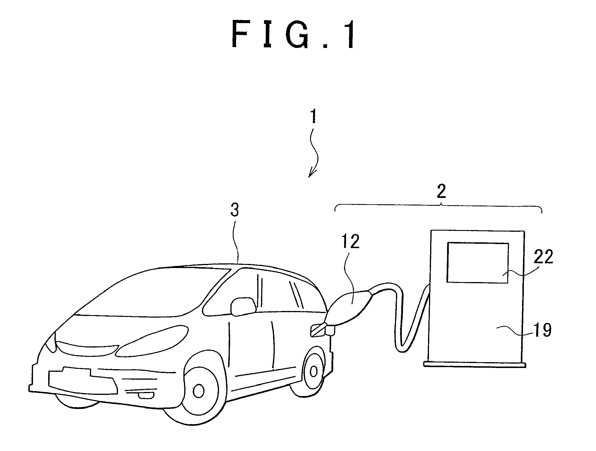
[0029]As shown in FIG. 1, the gas filling system 1 includes a hydrogen station 2, which functions as the gas station, for example, and a fuel cell vehicle 3 supplied with the hydrogen gas from the hydrogen station 2.

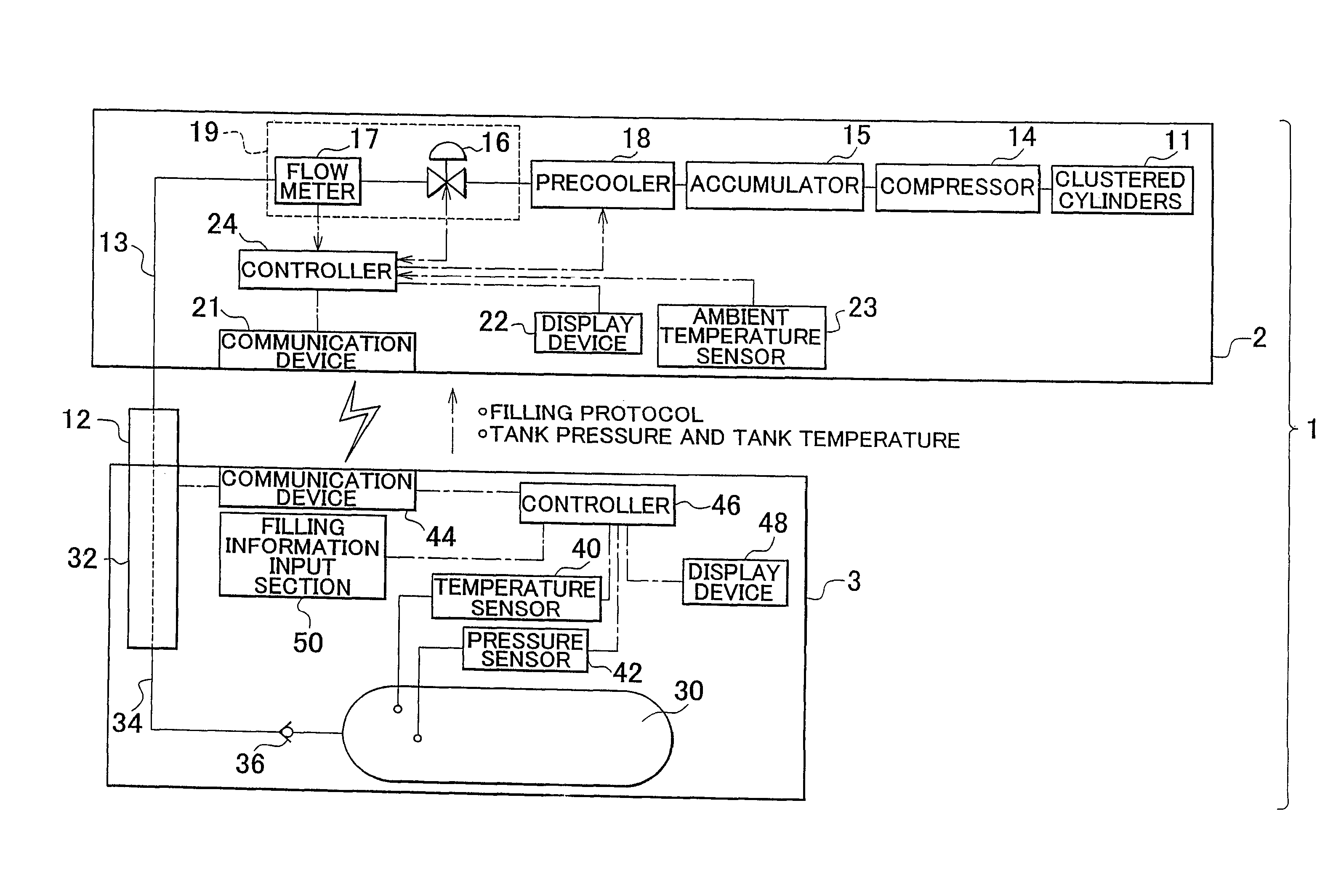
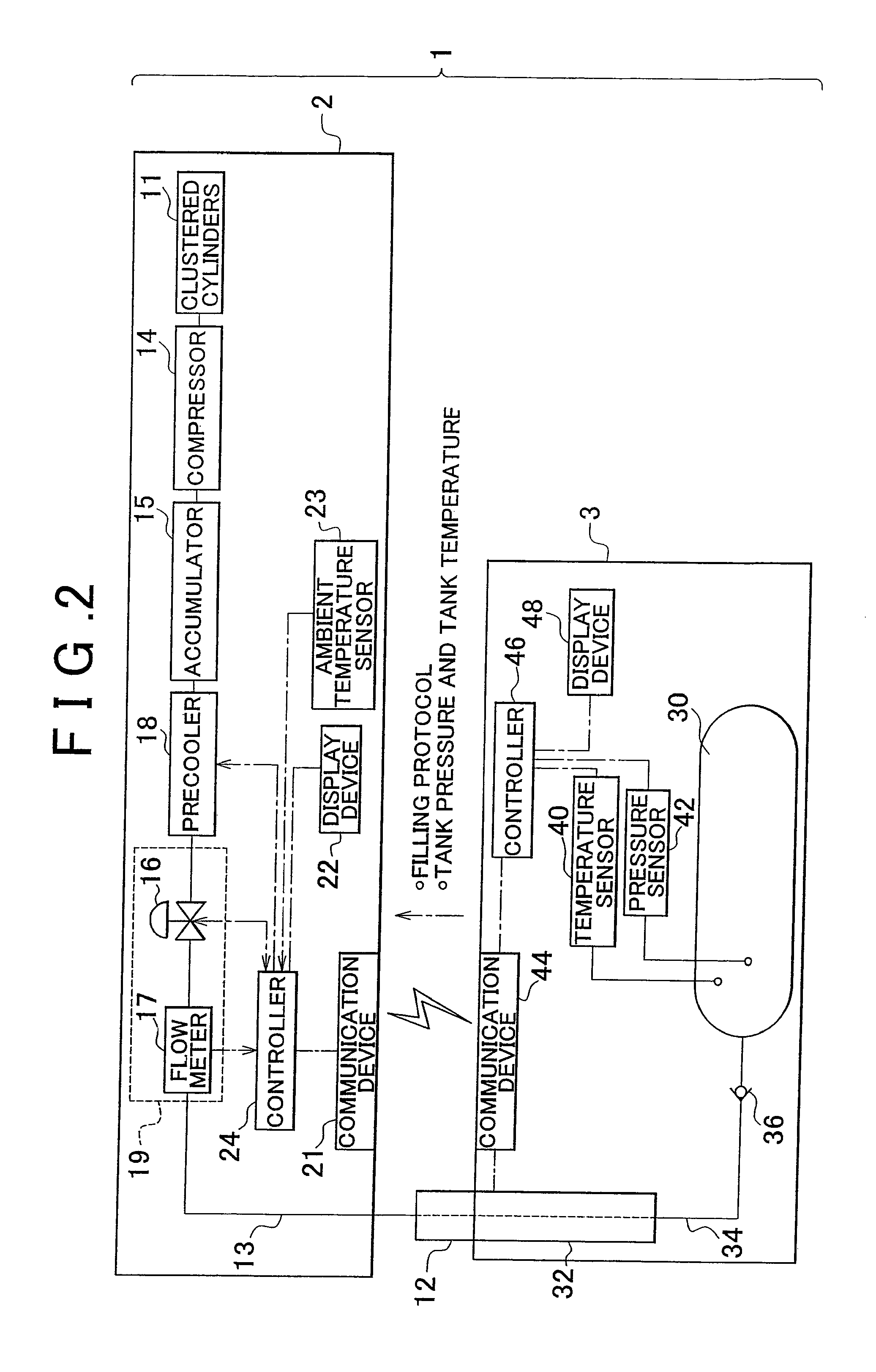
[0030]As shown in FIG. 2, the hydrogen station 2 has clustered cylinders (gas supply source) 11 that store hydrogen gas, a filling nozzle 12 that discharges hydrogen gas into an on-board gas tank 30, and a gas line 13 that connects the clustered cylin...


PUM

PropertyMeasurementUnit
temperatureaaaaaaaaaa
pressureaaaaaaaaaa

Abstract

A gas filling system includes a vehicle having a gas tank, and a gas station that supplies the gas tank with gas. The vehicle includes a controller having a filling protocol that specifies a method of control on the gas station side that is used when the gas is filled into the gas tank. The gas station controls filling of the gas into the gas tank according to the filling protocol provided by the controller. A filling protocol specific to the vehicle is used and therefore, it is made possible to perform filling adapted to the gas tank of the vehicle.

Description

[0001]This is a 371 national phase application of PCT / IB2010 / 001443 filed 16 Jun. 2010, claiming priority to Japanese Patent Application No. 2009- 177498 filed 30 Jul. 2009, the contents of which are incorporated herein by reference.BACKGROUND OF THE INVENTION[0002]1. Field of the Invention[0003]The invention relates to a gas filling system for filling gas from a gas station into a gas tank mounted on a vehicle.[0004]2. Description of the Related Art[0005]At the time of filling, a gas-fueled vehicle, on which a gas tank is mounted, such as a fuel cell vehicle, pulls into a gas station and the gas tank is filled with the fuel gas from a filling nozzle. In a gas filling system described in Japanese Patent Application Publication No. 2004-828211 (JP-A-2004-828211), the pressure and the temperature in the gas tank are detected via sensors before starting filling and the detected data are transmitted to the gas station. A central controller on the gas station side calculates the amount o...

Claims


Application Information

Patent Timeline
Patent Type & Authority Patents(United States)
IPC IPC(8): B65B3/26
CPCF17C2250/034Y02E60/321F17C2223/0123F17C5/007F17C2205/0335F17C2205/0326F17C2205/054F17C2250/0478F17C2250/0443F17C2250/0439F17C2250/072F17C2250/043F17C2223/036F17C2260/025F17C2221/012F17C2250/0636F17C2270/0184F17C2221/033F17C2265/065Y02E60/324F17C2260/024Y02E60/32
Inventor MORI, TOMOYUKI
Owner TOYOTA JIDOSHA KK
Why Eureka
Try Eureka