Adaptive deformable mirror for compensation of defects of a wavefront

a wavefront and deformation technology, applied in the field of production of adaptive deformation mirrors for compensating wavefront defects, can solve the problems of deformation of the mirror layer, previous state of the art demands, high manufacturing and mounting complexity, etc., and achieve the effect of reducing thermal deformation, easy compensating, and minimising thermal deformation

Active Publication Date: 2014-04-29
FRAUNHOFER GESELLSCHAFT ZUR FOERDERUNG DER ANGEWANDTEN FORSCHUNG EV +1
View PDF12 Cites 3 Cited by
  • Summary
  • Abstract
  • Description
  • Claims
  • Application Information

AI Technical Summary

Benefits of technology

[0008]The adaptive mirror according to the invention, in its simplest form, consists of a thin substrate layer, on the first surface of which a reflective layer is applied and the second surface of which is connected to at least one actuator. According to the invention, the substrate layer has a thickness of less than or equal to 1,000 μm. Such a small thickness of the substrate layer is necessary in order to avoid or at least to minimise thermal deformations due to the high power of the incident radiation. Since the heat expansion is proportional to the substrate thickness, the result, from the condition that the thickness of the substrate layer is 1,000 μm or less, is merely a small thermal deformation. Furthermore, the heat expansion coefficients of the materials used for the reflecting layer and the substrate layer are coordinated. Thermal deformations which nevertheless result are of such small dimensions that they can easily be compensated for by means of the actuators.
[0009]In order to further minimise thermal deformations, a substrate layer which has a thickness dependent upon the substrate and the modulus of elasticity thereof is advantageous. For example, the thickness with Al2O3 is at most 500 μm, with LTCC at most 400 μm and with silicon at most 700 μm. Furthermore, the thickness of the substrate layer is intended to be greater than or equal to 50 μm, preferably greater than or equal to 100 μm, in order to ensure a certain stability of the layer. The substrate layer and hence the entire adaptive mirror has a diameter in the range of 25 mm to 150 mm, in particular however in the range of 50 mm to 100 mm or 50 mm to 70 mm. The dimensions of the adaptive mirror used are based on the type of application and the substrate.
[0021]The reflecting layer can consist of a reflective metal mirror. Likewise, the reflective layer can consist of a reflective metal mirror having an additional multilayer layer which increases the degree of reflection. A further variant provides that the reflecting layer consists of a reflective metal mirror with an additional dielectric layer which increases the degree of reflection and lowers the degree of absorption.
[0025]The frames of the mirrors preferably consist of the same material as the respective substrate layer and can be structured in order to achieve increased flexibility and hence increased deflection.

Problems solved by technology

Because of the high power of the incident radiation and the absorption thereof, the result can be deformations of the mirror layer.
The previous state of the art demands high manufacturing and mounting complexity in order to connect the actuators or the active layers correspondingly to the mirror surface and / or in order to produce permanently the desired curvature of the mirrored layer.
Furthermore, because of the large layer thickness of the mirror surface, the result is thermal deformations which are caused by the high power of the incident radiation.
These thermal deformations must then be compensated for in conventional adaptive mirrors with the help of the actuators, in addition to the defects in the wavefront, which makes the precise compensation of defects in the wavefront difficult.

Method used


Image

  • Adaptive deformable mirror for compensation of defects of a wavefront
  • Adaptive deformable mirror for compensation of defects of a wavefront
  • Adaptive deformable mirror for compensation of defects of a wavefront

Examples


Embodiment Construction

[0031]A few examples of adaptive mirrors and arrangements according to the invention are provided in the following. There are shown:

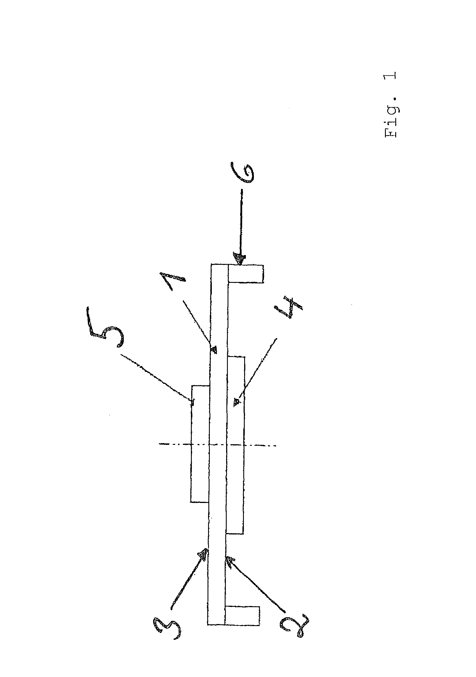
[0032]FIG. 1 a basic construction of an adaptive mirror according to the invention,

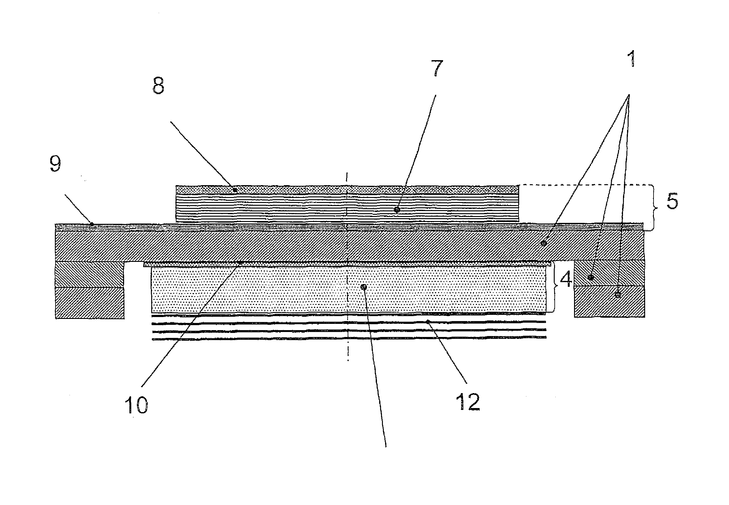
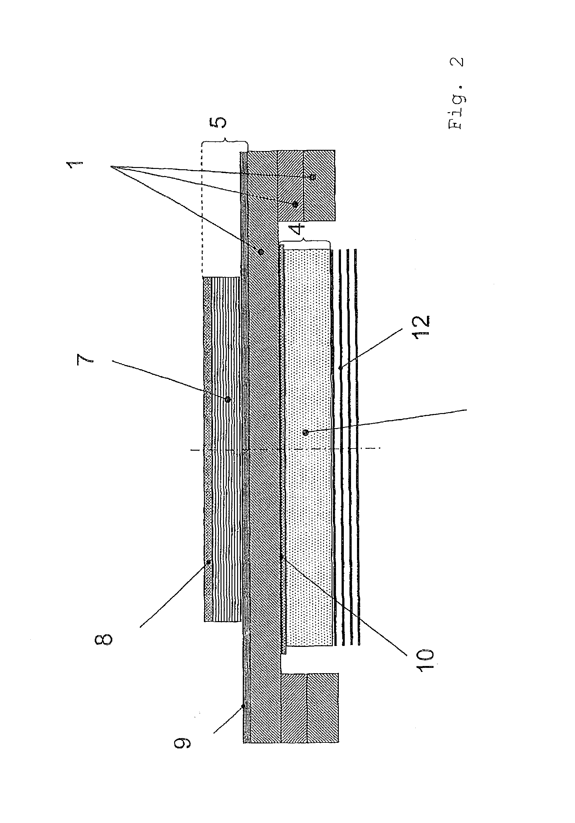
[0033]FIG. 2 a construction of an embodiment of an adaptive mirror according to the invention, and

[0034]FIG. 3A-3D a plan view on an adaptive mirror with various actuation methods via differently disposed partial electrodes.

[0035]FIG. 1 shows the cross-section through an adaptive mirror as is described in the present invention. The same or similar reference numbers here thereby describe the same or similar elements in the following Figures.

[0036]The adaptive mirror is constructed from a substrate layer 1 which is at most 1,000 μm thick, on the first surface 2 of which a reflecting layer 4 and on the second surface 3 of which at least one actuator 5 is applied. At the edges of the substrate layer 1 on the first surface 2 thereof, a mounting 6 is fitted and has for LTCC the...


PUM

PropertyMeasurementUnit
thicknessaaaaaaaaaa
thicknessaaaaaaaaaa
thicknessaaaaaaaaaa

Abstract

An adaptive mirror that includes a substrate layer, on the first surface of which a reflecting layer and on the second surface of which at least one actuator is disposed. The substrate layer has a thickness of less than or equal to 1,000 μm and the mirror having at least one further metallization for thermal compensation, as a result of which a thermal deformation of the mirror is avoided or preadjusted such that the desired curvature is set as a function of the reflected power.

Description

PRIORITY INFORMATION[0001]The present invention is a 371 National Phase Application of International Application No. PCT / EP2009 / 001967, filed on Mar. 17, 2009, that claims priority to German Application No. DE 102008014615.3, filed on Mar. 17, 2008. Both applications are incorporated herein in their entireties.BACKGROUND OF THE INVENTION[0002]The present invention relates to the production of an adaptive deformable mirror for compensation of defects of a wavefront.[0003]Adaptively deformable mirrors are used in various fields of optics, thus e.g. in terrestrial or extraterrestrial applications but also in experiments with electromagnetic radiation with high power, as is emitted by high-power lasers and / or high-power laser processes or in experiments with low or extreme ultraviolet radiation.[0004]In particular for use with low or extreme ultraviolet radiation, various embodiments of adaptive mirrors have been developed. The basic idea resides in a mirror surface being deformed by me...

Claims


Application Information

Patent Timeline
Patent Type & Authority Patents(United States)
IPC IPC(8): G02B7/182G02B5/08
CPCG02B26/06Y10T156/1052
Inventor BRUCHMANN, CLAUDIABECKERT, ERIKPESCHEL, THOMASDAMM, CHRISTOPHGEBHARDT, SYLVIA
Owner FRAUNHOFER GESELLSCHAFT ZUR FOERDERUNG DER ANGEWANDTEN FORSCHUNG EV
Why Eureka
Try Eureka