Electrical connection between conductive elements

a technology of electrical connection and conductive elements, which is applied in the direction of mixers, coupling device connections, cleaning of hollow articles, etc., can solve the problem that conductive elements will not lead to an appropriate electrical path therebetween, and achieve the effect of improving the ease of connection and improving the overlap of connections

Active Publication Date: 2014-04-29
PFAUDLER WERKE
View PDF11 Cites 11 Cited by
  • Summary
  • Abstract
  • Description
  • Claims
  • Application Information

AI Technical Summary

Benefits of technology

[0010]It is further possible to provide a sealing element, which is preferably airtight and / or watertight, in a region near the conductive paste in order to isolate this from the surrounding environment of the conductive elements. In particular, this sealing element can be placed such that when the two conductive elements are connected together in some manner, the sealing element forms a bridge between these two conductive elements and leads to an appropriate seal isolating the conductive paste from the environment surrounding the conductive elements. It is further advantageous if the seal is to degree compressed between the two conductive elements, thus ensuring that no leakage gaps can form across the seal.
[0014]If one of the elements is intended to frictionally engage with the second or more elements, this can be achieved by cooling one of the elements to reduce its size slightly to allow it to be positioned within an appropriate holding portion of the other elements. Once the cooled element starts to heat up it will naturally expand to its original size, and thus can be frictionally held within the other electrically conductive elements. Clearly, if the mechanism of fixing together the conductive elements is by this shrink-fitting technique, the sealing element will be brought under a compression force between the one or more elements, thus compressing the sealing element and leading to a good isolation seal.
[0018]As will also be clear, it is possible to use a channel, if provided, to actually remove the conductive paste from the conductive region. If the conductive elements have been shrink-fit together and the elements are to be disengaged from each other, removal of the conductive paste can improve the disassembly process. This could readily be achieved by use of an appropriate solvent and some sort of syringe, in order to dose the solvent through the channel into the region comprising the conductive paste.
[0021]Additional discussion is presented relating to the possibility of providing elongate electrical connections passing through the non-conductive coatings on the electrically conductive elements. These elongate structures can be used to improve the overlap of the connections during attachment of the conductive elements together. Markings may also be provided which show the location of the grooves, in order to improve the ease of connection.

Problems solved by technology

Clearly, if the outer surface is provided with a non-conductive coating, simple connection together of the conductive elements will not lead to an appropriate electrical path there-between.

Method used


Image

  • Electrical connection between conductive elements
  • Electrical connection between conductive elements
  • Electrical connection between conductive elements

Examples


Embodiment Construction

[0035]In the following, the concepts of the disclosure are described with relation to an agitator assembly 1. This is, of course, by way of example only. Indeed, the following methods and products can, as will be appreciated by the skilled person, readily be applied to any connection between two or more electrically conductive items which have an insulation coating thereon.

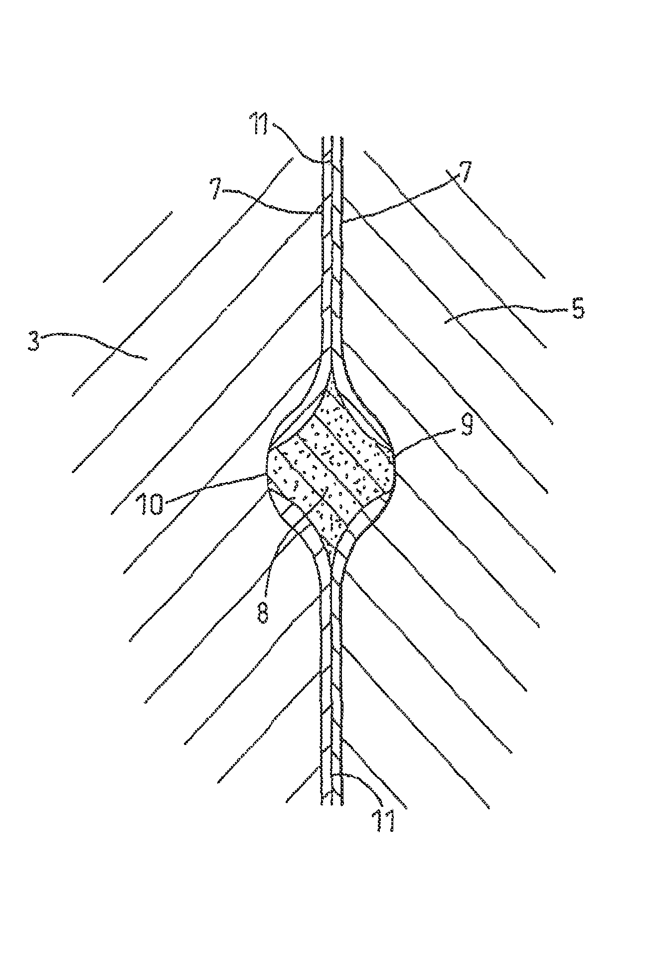
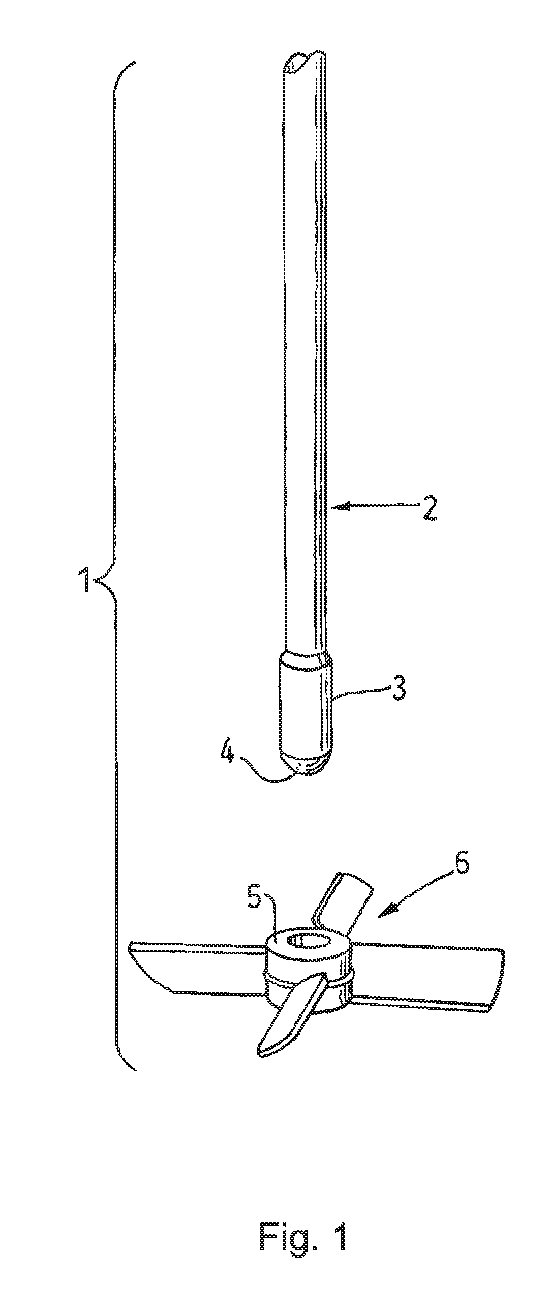
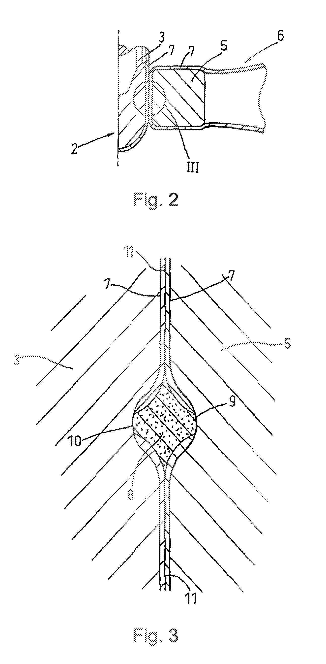
[0036]With reference to FIG. 1, an agitator assembly 1 comprises a drive shaft 2 with an enlarged end section 3 and closed end 4 for fitment into a hub 5 of an agitator blade assembly 6. As shown in FIG. 2, the whole of the exterior surfaces of the drive shaft 2 and the agitator blade assembly 6 are coated with a layer of enamel or glass 7, the glass being bonded thereto by conventional practice well known to those with skill in the art. The agitator assembly is then assembled by the shrink-fitment of the agitator blade assembly 6 to the enlarged end section 3 of the drive shaft, again in accordance with conventio...


PUM

PropertyMeasurementUnit
angleaaaaaaaaaa
angleaaaaaaaaaa
temperatureaaaaaaaaaa

Abstract

A method of forming an electrically conductive connection between two or more electrically conductive elements (2, 6) is provided, as is the resulting connection. Wherein the two or more electrically conductive elements (2, 6) are coated with a non-conductive coating (7), wherein an at least partially electrically conductive pasty medium (8) is located in a region (12) between the electrically conductive elements (2, 6) at regions of the electrically conductive elements (2, 6) which are substantially free from any non-conductive coating (7). The method comprising positioning one or more sealing elements (20) such that they completely isolate the partially electrically conductive pasty medium (8), such that after the electrically conductive elements (2, 6) are connected together, the sealing element (20) is held, and preferably compressed, between the electrically conductive elements (2, 6) and form a seal separating the at least partially electrically conductive pasty medium (8) from the surrounding environment.

Description

CROSS-REFERENCE TO RELATED APPLICATIONS[0001]The present application is the U.S. national stage application pursuant to 35 U.S.C. §371 of International Application No. PCT / EP2010 / 054654, filed Apr. 8, 2010, which application claims benefit of European Application No. EP09169068.5, filed Aug. 31, 2009.BACKGROUND OF THE INVENTION[0002]The present invention relates to a method of producing an electrically conductive connection between metallic components which have a non-conductive coating. In particular, the invention relates to a method of producing an electrically conductive coating between metallic components which are coated with an enamel, glass or similar coating that is resistant to corrosive media.[0003]In the chemical and pharmaceutical industries, it is common for agitators to be used in corrosive environments. In such cases, the agitator blades and the agitator shaft to which the blades are connected are usually coated with materials such as enamel or glass, which are stabl...

Claims


Application Information

Patent Timeline
Patent Type & Authority Patents(United States)
IPC IPC(8): H01R9/24
CPCB01F7/001Y10T29/49153B01F7/00341H01R4/64Y10T29/49117H01R4/66H01R13/5216B01F27/071B01F27/113
Inventor STOLTZ, BRUNOENDRESS, JOCHENTHEILIG, MICHAELHEINZMANN, MATTHIAS
Owner PFAUDLER WERKE
Why Eureka
Try Eureka