Switched reluctance and PM brushless DC motor drive control for electric vehicle application

a brushless dc motor and electric vehicle technology, applied in the direction of dynamo-electric converter control, magnetic circuit rotating parts, magnetic circuit shape/form/construction, etc., can solve the problem that one of the significant cost elements of the power converter circuit is the motor drive, and achieve the effect of enhancing the electromagnetic torque operation of the machin

Inactive Publication Date: 2014-05-06
REGAL BELOIT AMERICA
View PDF1 Cites 10 Cited by
  • Summary
  • Abstract
  • Description
  • Claims
  • Application Information

AI Technical Summary

Benefits of technology

[0004]The control techniques relate to the operation of the power converter during motoring and provide enhanced electromagnetic torque operation of the machine. One control technique provides ripple-free operation of the electric machine.

Problems solved by technology

One of the significant cost elements in a motor drive is the power converter circuit, particularly in the number of power devices such as transistors and power diodes.

Method used


Image

  • Switched reluctance and PM brushless DC motor drive control for electric vehicle application
  • Switched reluctance and PM brushless DC motor drive control for electric vehicle application
  • Switched reluctance and PM brushless DC motor drive control for electric vehicle application

Examples


first embodiment

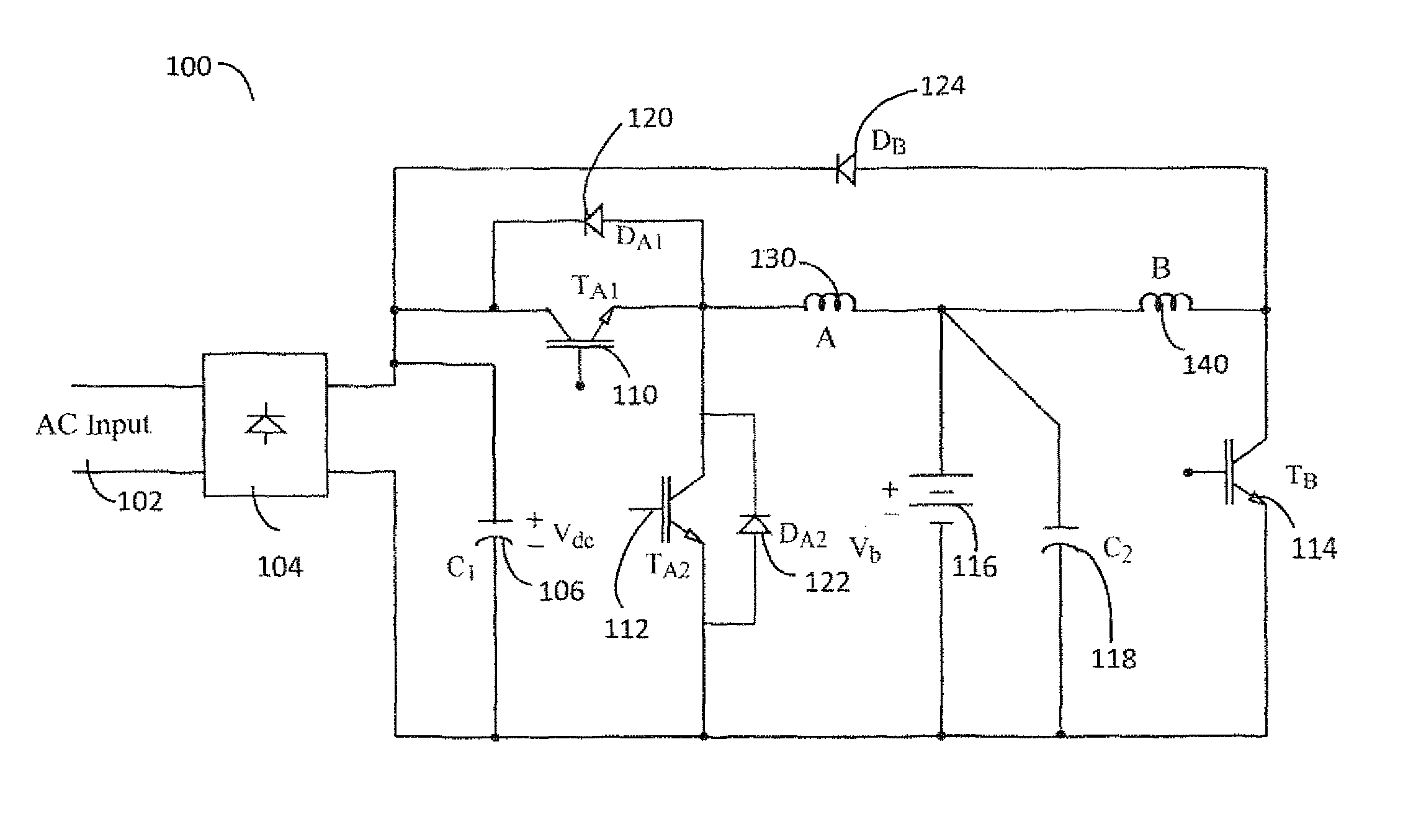
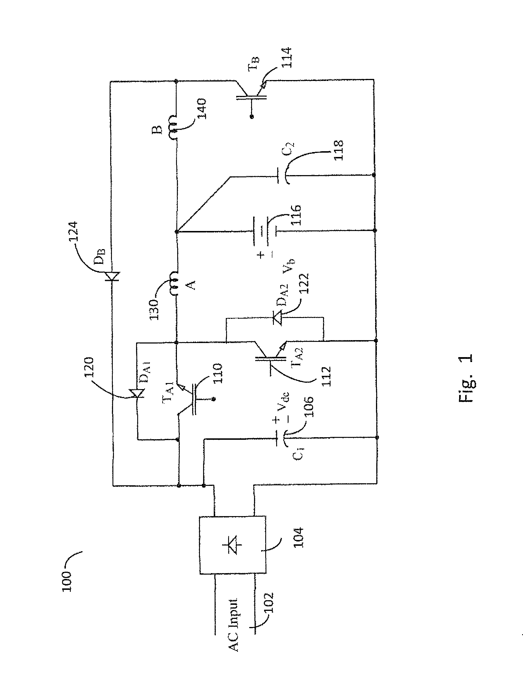
[0015]FIG. 1 illustrates a power converter. Power converter 100 receives a single-phase, alternating current (ac) supply voltage 102 provided by a utility grid. Supply voltage 102 is rectified through a single-phase, bridge rectifier 104 and filtered with a capacitor C1 106, so as to produce a direct current (dc) voltage, Vdc, across capacitor 106. Vdc is also referred to as a de link voltage. Power converter 100 provides operational modes of battery-bank charging, motoring, and regeneration.

[0016]During the charging mode of operation, Vdc charges a battery bank 116 via a buck converter, which comprises a transistor 110, diode 122, and phase-A winding 130. The charging of battery bank 116 is accomplished by changing the on-time duration of transistor 110, using pulse width modulation (PWM) control, so that current in phase-A winding 130 is regulated to a desired charging current of battery bank 116. Transistor 110 is turned on and off with a duty cycle of d so that current conducted...

second embodiment

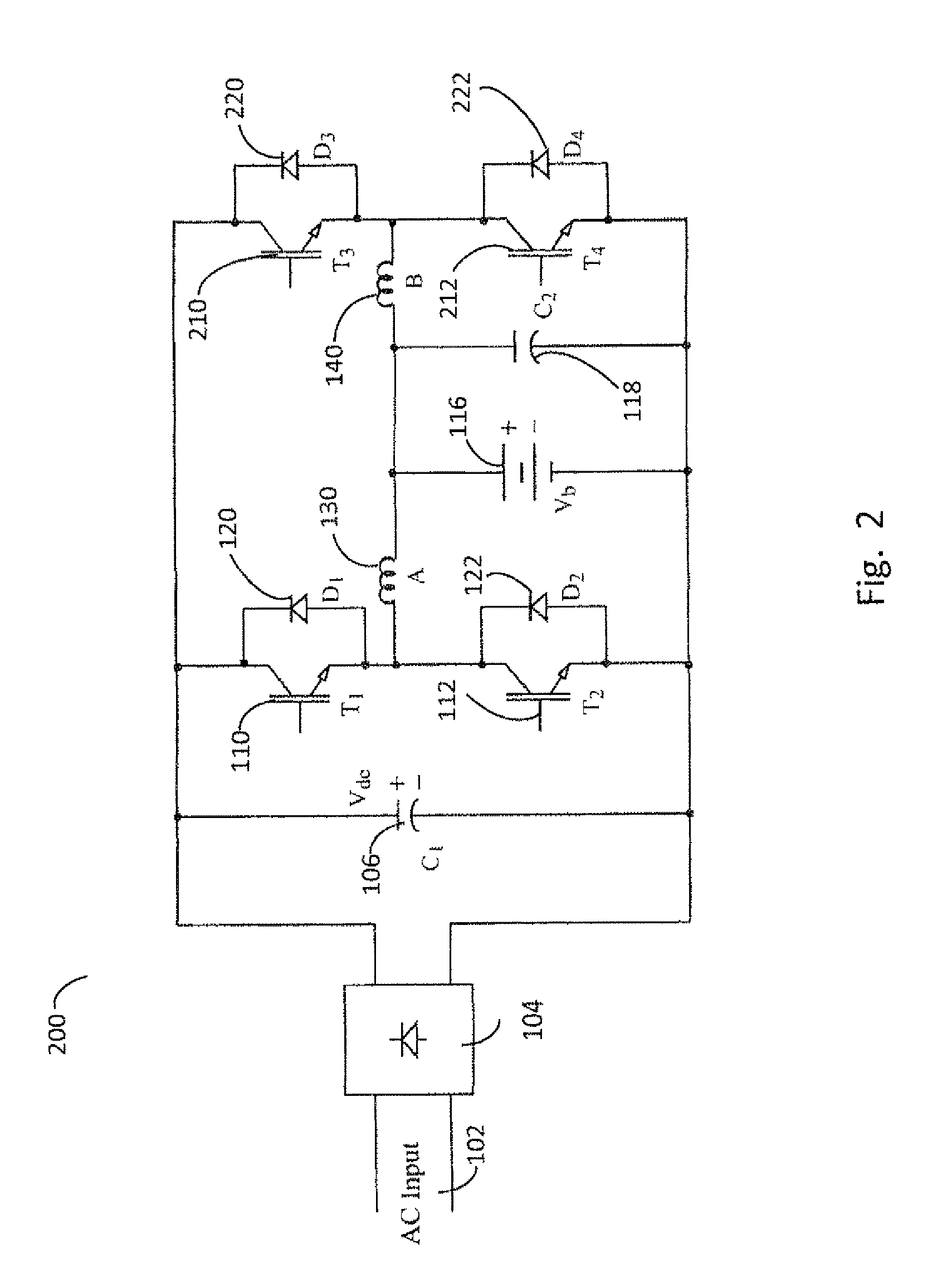
[0022]FIG. 2 illustrates a power converter. Power converter 200 has transistors 110 and 112 with anti-parallel diodes 120 and 122, respectively, across them. Transistors 110 and 112 and diodes 120 and 122 constitute an inverter phase leg, as do transistors 210 and 212 and diodes 220 and 222. Together, these two sets of phase legs of an inverter constitute a single-phase H-bridge inverter, which is available in the form of an intelligent power module with gate drivers and protection circuits for over-current, under-voltage, and over-voltage operation; they are compact in size and very cost effective for mass production.

[0023]Transistor 110, phase-A winding 130, battery bank 116, capacitor 106, and diode 122 are used as a buck power circuit for charging battery bank 116 from the dc source voltage, Vdc. Similarly transistor 210, phase-B winding 140, battery bank 116, capacitor 106, and diode 222 serve as another buck power converter circuit to charge battery bank 116 from capacitor 106...


PUM


Abstract

A method of operating an electrical machine having first and second phase windings. The method includes: (1) applying positive first current to the first phase winding while the first phase winding's back electromotive force (emf) is positive; (2) applying negative second current to the first phase winding while the first phase winding's back emf is negative; and (3) applying positive third current to the second phase winding while the second phase winding's back emf is positive. The first current is conducted through a circuit composed of a battery, the first phase winding, and a first switch. The second current is conducted through a circuit composed of a first capacitive storage element, the battery, the first phase winding, and a second switch, and the third current is conducted through a circuit composed of the battery, the second phase winding, and a third switch.

Description

[0001]This application claims priority to U.S. provisional application 61 / 409,638, filed on Nov. 3, 2010, the content of which is incorporated herein by reference.BACKGROUND OF THE RELATED ART[0002]Low cost motor drives in vehicle applications, such as electric bikes (hereafter referred to as E-Bikes) operated with battery-stored energy, are sought after because of their positive impact on the environment, the existing mass market of electric bikes, and the limited financial resources of the user community in countries such as China, India, and other developing nations. One of the significant cost elements in a motor drive is the power converter circuit, particularly in the number of power devices such as transistors and power diodes. Economy in the use of power devices translates into reduced control circuit components, such as gate drives, logic power supplies, and device protection circuits; such economy also leads to reduced printed circuit board area, heat-sink volume, and weig...

Claims


Application Information

Patent Timeline
Patent Type & Authority Patents(United States)
IPC IPC(8): H02P1/00
CPCH02K15/12H02K1/24Y02T10/641G01B11/26Y02T10/64H02K1/32H02K1/20H02K1/14H02K1/146H02K1/148
Inventor RAMU, KRISHNAN
Owner REGAL BELOIT AMERICA
Why Eureka
Try Eureka