
Driving device and method for driving a load, in particular an LED assembly

一种驱动负载、设备的技术,应用在电气元件、半导体灯的使用、电致发光光源等方向,能够解决无光、放电电流未通过等问题

Active Publication Date: 2013-12-18
SIGNIFY HLDG BV
View PDF10 Cites 12 Cited by
  • Summary
  • Abstract
  • Description
  • Claims
  • Application Information

AI Technical Summary

Problems solved by technology

[0006] All of these TLD systems have a common disadvantage: no light output if the (rectified) mains voltage drops below the voltage of the "shortest" high voltage LED string
[0010] Adding a fill-in capacitor helps maintain the light output around the zero crossing of the mains voltage (reduced flicker), but creates dimmer problems like multi-triggering because its discharge current is not passing through the mains branch

Method used


Image

  • Driving device and method for driving a load, in particular an LED assembly
  • Driving device and method for driving a load, in particular an LED assembly
  • Driving device and method for driving a load, in particular an LED assembly

Examples


Embodiment Construction

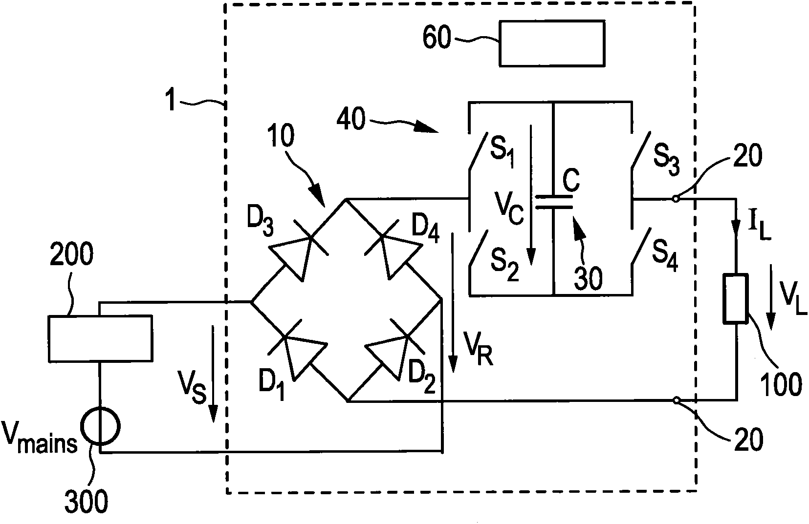
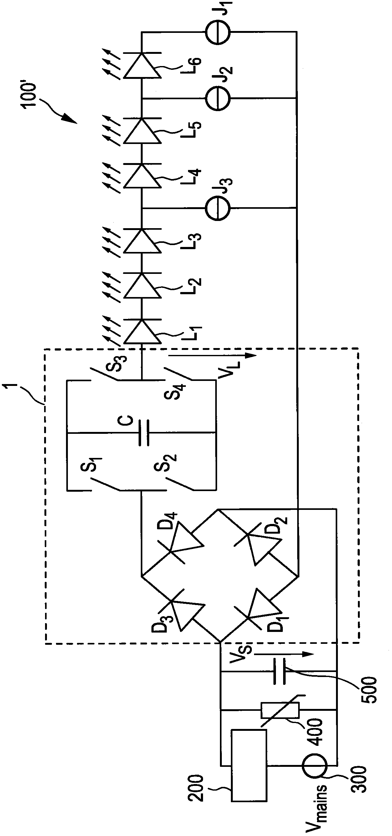
[0081] figure 1 A first embodiment of a driver device 10 (also called a driver circuit) according to the invention for driving a load 100, in particular an LED assembly comprising one or more LEDs, is shown. Said driver device 1 comprises means for passing the received AC mains voltage V S rectified to generate a rectified supply voltage V R The rectifier unit 10, the mains voltage supply provides the mains voltage V mains . The drive voltage V for driving the load 100 is provided at a pair of load terminals 20 L . The capacitive storage unit 30 is coupled between the rectifier unit 10 and the load 100 for storing the electric energy provided by the rectifier unit 10 and providing electric energy to the load 100 . A bridge switching unit 40 is coupled between the rectifier unit 10 and the load 100 for switching the capacitive storage unit 30 with the desired polarity into the load current path from the rectifier unit 10 to the load 100 and for switching the capacitive sto...


PUM


Abstract

Driver device and a corresponding driving method for driving a load, in particular an LED assembly comprising one or more LEDs. To provide a better performance, better cost-efficiency, improved power factor and reduced losses, a driver device (1, 1', 2, 2') is provided comprising a rectifier unit (10) for rectifying a received AC supply voltage (VS), load terminals (20) for providing a drive voltage (VL) and / or a drive current (IL) for driving said load, a capacitive storage unit (30) coupled between said rectifier unit and said load terminals for storing electrical energy provided by said rectifier unit and providing electrical energy to said load, and a bridge switching unit (40); coupled between said rectifier unit and said load for switching said capacitive storage unit into a load current path from said rectifier unit to said load terminals with a desired polarity and for switching said capacitive storage unit out of said load current path.

Description

technical field [0001] The invention relates to a driver device for driving a load, in particular an LED assembly comprising one or more LEDs, and a corresponding driving method. Background technique [0002] Light-emitting diodes (LEDs) are changing the lighting world. Its high and still increasing luminous efficacy, its long life, its small form factor, its low weight, its robustness, its ease of manufacture, etc. set the stage for the lighting industry to switch from incandescent lamps. The driving force of LED lights. However, the non-linear (nearly exponential) I-V curve of the LED, its low operating voltage (several volts) and its fast current-to-light output transfer response are critical when the lamp will be powered from mains voltage (eg 115V AC or 230V AC). A number of problems arise including light output flicker and voltage imbalance. [0003] Ideally, a DC must be supplied to the LED because the transfer from current to light output is nearly linear. One so...

Claims


Application Information

Patent Timeline
Patent Type & Authority Applications(China)
IPC IPC(8): H05B33/08H05B44/00
CPCH05B45/40H05B45/48Y02B20/30H05B45/38H05B45/59
Inventor H·J·G·拉德马赫尔P·G·布兰肯Y·邱陶海敏R·范兰格维尔德R·库尔特
Owner SIGNIFY HLDG BV
Learn More