Supercharge Your Innovation With Domain-Expert AI Agents!

Touch panel

a technology of touch panel and display panel, applied in the field of touch panel, can solve the problems of increasing cost and control circuit complexity, still degrading display brightness, etc., and achieve the effect of reducing manufacturing cos

Active Publication Date: 2014-05-06
E INK HLDG INC
View PDF10 Cites 0 Cited by
  • Summary
  • Abstract
  • Description
  • Claims
  • Application Information

AI Technical Summary

Benefits of technology

[0008]Another objective of the present invention is to disclose a touch panel, of which the touch sensing module can be made of cheaper plastics and general metal to reduce manufacturing cost.
[0010]To make it easier for our examiner to understand the objective of the invention, its structure, innovative features, and performance, we use a preferred embodiment together with the accompanying drawings for the detailed description of the invention.

Problems solved by technology

However, if the display panel is a reflective one—utilizing surrounding lighting for illumination, then the illumination attenuation caused by the touch module can still degrade the display brightness, even though the touch module is made of transparent materials.
However, in implementing the touch module, either utilizing transparent materials like glass or ITO, or employing a non-contact mechanism like capacitive or optical sensing, can increase the cost and the control circuit complexity.

Method used


Image

  • Touch panel
  • Touch panel

Examples


Embodiment Construction

[0013]The present invention will be described in more detail hereinafter with reference to the accompanying drawings that show the preferred embodiment of the invention.

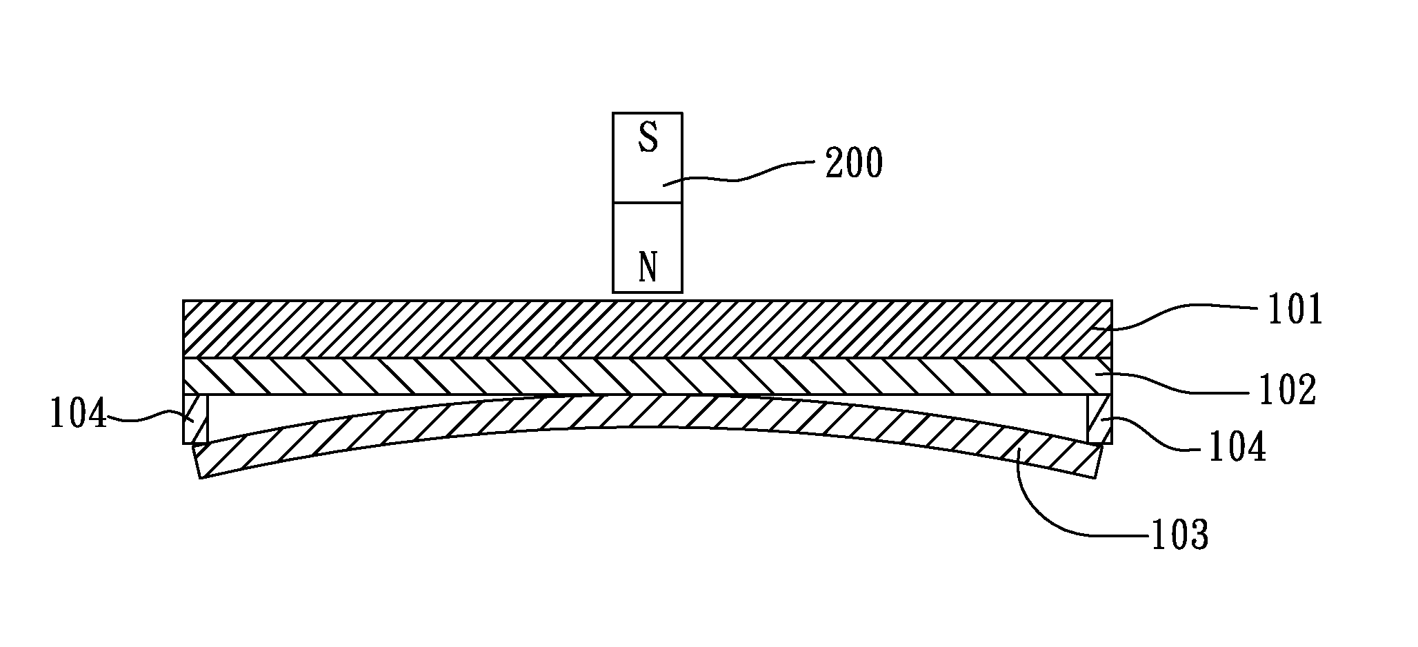
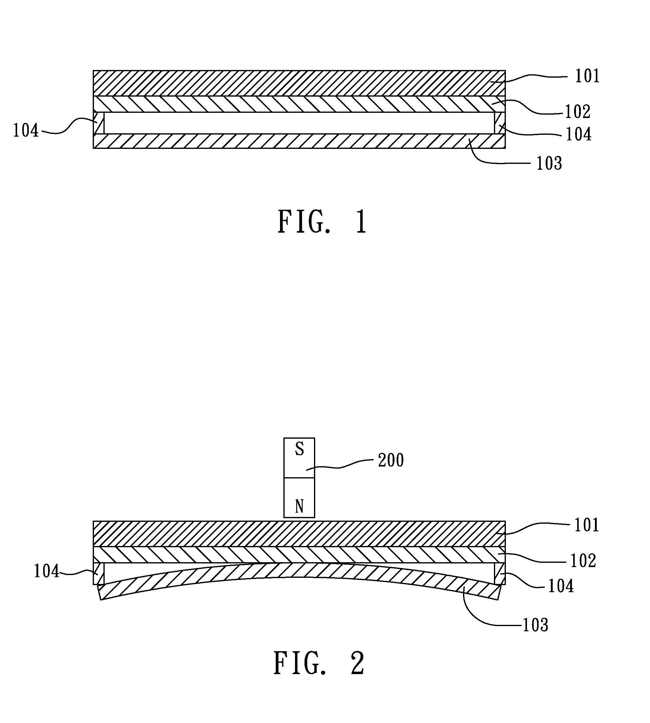
[0014]Please refer to FIG. 1, which illustrates a structural cross-section of a touch panel according to a preferred embodiment of the present invention. As illustrated in FIG. 1, the touch panel includes an electronic paper panel 101, a first conductive layer 102, a second conductive layer 103, and a plurality of insulating spacers 104.

[0015]The electronic paper panel 101, having a display plane and an interface plane—the interface plane underlying the display plane, is used to display an image on the display plane, wherein the data for the image is received from an electronic paper input port (not illustrated in the figure). The electronic paper panel 101 can be implemented with an electrophoresis display, a MEMS (Micro Electro Mechanical Systems) display, a cholesteric liquid crystal display, an electrowetting dis...


PUM


Abstract

A touch panel, operated by a magnetic stylus, including: a display panel, having a display plane and an interface plane, the interface plane underlying the display plane; and a sensing assembly, underlying the display panel, having a first conductive layer, a second conductive layer, and a plurality of insulating spacers, the first conductive layer underlying the interface plane, and the insulating spacers being placed between the first conductive layer and the second conductive layer to divide the first conductive layer and the second conductive layer into a plurality of first conductive segments and a plurality of second conductive segments respectively, wherein one of the second conductive segments will be bent upward by a magnetic force to electrically connect with one of the first conductive segments when the magnetic stylus is applied thereto.

Description

BACKGROUND OF THE INVENTION[0001]1. Field of the Invention[0002]The present invention relates to a touch panel, especially to a touch panel of which the touch input function is realized by the effect of a magnetic force.[0003]2. Description of the Related Art[0004]As is known, a touch module, if placed over a display panel, has to be implemented with transparent materials like glass and ITO (Indium Tin Oxside), so as not to hinder the display of the display panel. However, if the display panel is a reflective one—utilizing surrounding lighting for illumination, then the illumination attenuation caused by the touch module can still degrade the display brightness, even though the touch module is made of transparent materials. As such, the reflective display panel is placed in general over the touch module.[0005]Besides, to avoid damaging the display panel which overlies the touch module, when performing a touch input, non-contact mechanism like capacitive or optical sensing is commonl...

Claims


Application Information

Patent Timeline
Patent Type & Authority Patents(United States)
IPC IPC(8): G06F3/041
CPCG06F3/03545G06F3/045
Inventor CHUANG, KAI-CHENG
Owner E INK HLDG INC
Features
  • R&D
  • Intellectual Property
  • Life Sciences
  • Materials
  • Tech Scout
  • Unparalleled Data Quality
  • Higher Quality Content
  • 60% Fewer Hallucinations
Learn More