Display device and electronic apparatus

a technology of electronic equipment and display device, which is applied in the field of display device and electronic equipment, can solve the problems of reducing the brightness and chroma of chromatic color (yellow), difficulty in displaying bright yellow, and affecting the display effect of the display device, and achieves the effect of high contras

Active Publication Date: 2014-05-06
E INK CORPORATION
View PDF7 Cites 25 Cited by
  • Summary
  • Abstract
  • Description
  • Claims
  • Application Information

AI Technical Summary

Benefits of technology

[0008]An advantage of some aspects of the invention is to provide a display device capable of exhibiting high contrast and displaying clear colors, and an electronic apparatus using the same.

Problems solved by technology

However, in the display device described in JP-A-2009-192637, the black first particles are collected on the upper electrode side together with the yellow second particles in the yellow display state, and thus, due to the influence of black, it is difficult to display bright yellow, that is, the original color of the second particles.
That is, in the display device described in JP-A-2009-192637, the contrast decreases, the brightness and chroma of chromatic color (yellow) decrease, and thus there is a problem that it is difficult to exhibit excellent display properties.

Method used


Image

  • Display device and electronic apparatus
  • Display device and electronic apparatus
  • Display device and electronic apparatus

Examples


first embodiment

[0060]First, a first embodiment of the display device of the invention will be described.

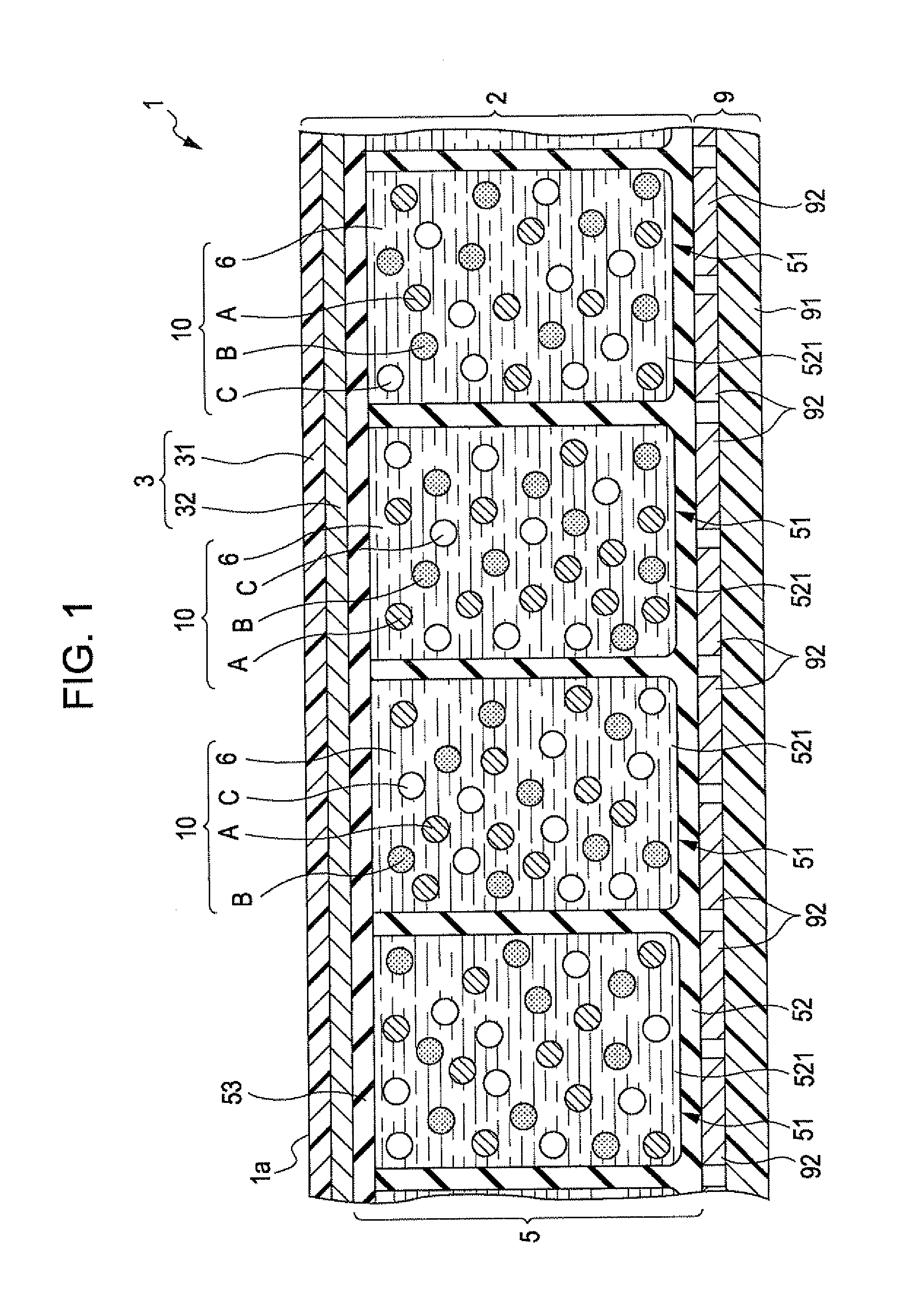
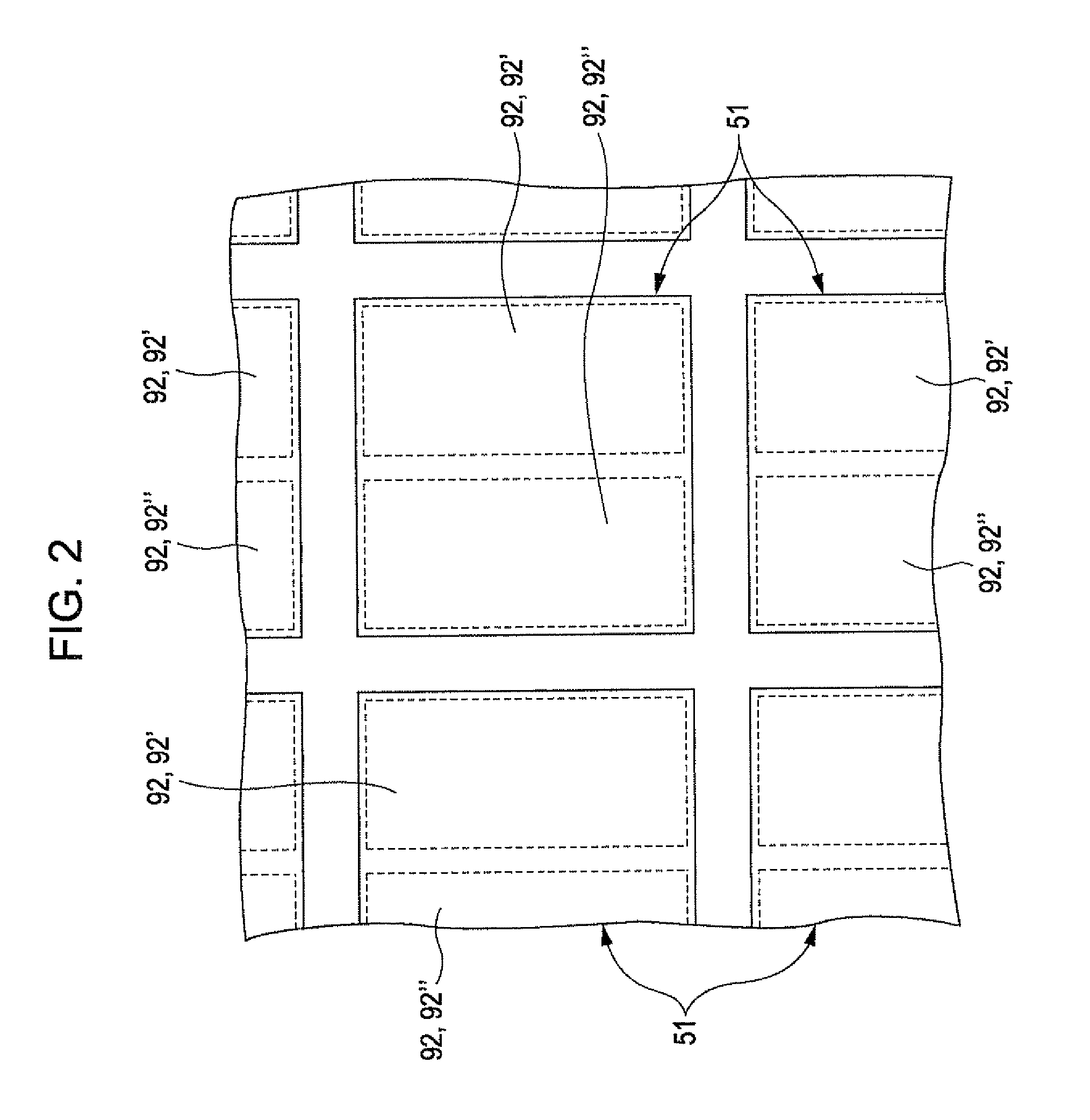
[0061]FIG. 1 is a cross-sectional view schematically illustrating the display device according to the first embodiment of the invention, FIG. 2 is a plan view of the display device shown in FIG. 1, FIG. 3A and FIG. 3B are plan views illustrating modified examples of a front side electrode shown in FIG. 2, FIG. 4 is a schematic diagram illustrating a first particle and a second particle, FIG. 5A, FIG. 5B, FIG. 5C, FIG. 9A, and FIG. 9B are diagrams illustrating operation voltages of the display device shown in FIG. 1, and FIG. 6, FIG. 7, FIG. 8, and FIG. 10 are schematic diagrams illustrating an operation of the display device shown in FIG. 1. Hereinafter, for description, the upside of FIG. 1 is “upper” and the downside is “lower”.

1. Configuration of Display Device

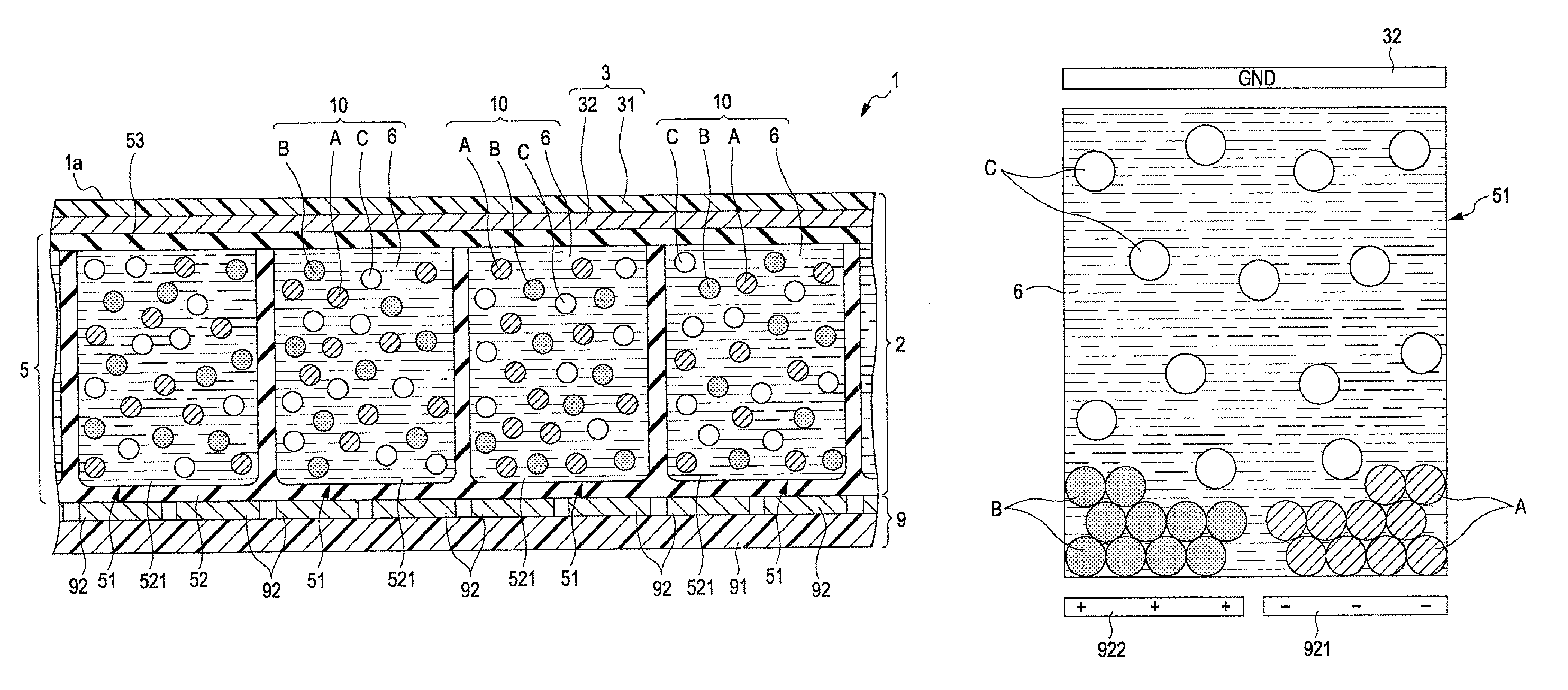
[0062]The display device 1 shown in FIG. 1 is provided with a display sheet (front plane) 2, and a circuit board (back plane) 9.

[0063]...

second embodiment

[0129]Next, a display device according to a second embodiment of the invention will be described.

[0130]FIG. 11 is a cross-sectional view schematically illustrating the display device according to the second embodiment of the invention.

[0131]Hereinafter, the display device according to the second embodiment will be described, but differences from the above-described embodiment are mainly described, and the description of the same contents is omitted.

[0132]The display device 1A according to the embodiment has the same configuration as that of the above-described first embodiment, except for the number of cells constituting one pixel.

[0133]As shown in FIG. 11, in the display device 1A of the embodiment, one pixel is formed of three cells 51 (the first cell 51A, the second cell 51B, and the third cell 51C).

[0134]In the first cell 51A, the color of the first particles A is red, and the color of the second particles B is cyan which has a complementary relation with red. In the second cell...


PUM

PropertyMeasurementUnit
particle diameteraaaaaaaaaa
voltageaaaaaaaaaa

Abstract

A display device includes a display layer provided with a cell in which first particles, second particles, and third particle with colors different to each other are contained, a front side electrode provided on the front side of the display layer, and a first and second back side electrodes provided corresponding to the cell on the back side of the display layer. The first particles are charged. The second particles have a color in a complementary color relation to that of the first particles, are charged with the opposite polarity to that of the first particles, and have a smaller amount of charge than that of the first particles. In the display device, a part where the first particles and the second particles are disproportionately located is set with the third particles dispersed in the cell, to change a color in the cell viewed from the front side electrode side.

Description

BACKGROUND[0001]1. Technical Field[0002]The present invention relates to a display device and an electronic apparatus.[0003]2. Related Art[0004]An electrophoretic display using electrophoresis of particles, which constitutes an electronic paper image display unit is known (e.g., see JP-A-2009-192637). The electrophoretic display has excellent portability and power-saving properties, and is particularly suitable as an electronic paper image display unit.[0005]In JP-A-2009-192637, a display device is disclosed, which includes a plurality of cells, two electrodes (upper electrodes) provided on one side (upside) of each cell, and a lower electrode provided on the other side (downside) of each cell. A dispersion liquid formed by dispersing three kinds of particles in a dispersion medium is sealed in each cell. The three kinds of particles include negatively charged black first particles, negatively charged yellow second particles, and positively charged white third particles.[0006]In the...

Claims


Application Information

Patent Timeline
Patent Type & Authority Patents(United States)
IPC IPC(8): G02B26/00G02F1/167
CPCG02F2001/1678G02F2203/34G02B26/026G02B26/00G02F1/167
Inventor KOMATSU, HARUNOBU
Owner E INK CORPORATION
Why Eureka
Try Eureka