Color display device

a display device and color technology, applied in the field of color display devices, can solve the problems of inability to choose a color display device, inability to adjust the color, and inability to meet the needs of color filters, so as to eliminate the need for color filters

Active Publication Date: 2014-05-06
E INK CORPORATION
View PDF111 Cites 175 Cited by
  • Summary
  • Abstract
  • Description
  • Claims
  • Application Information

AI Technical Summary

Benefits of technology

[0010]The present invention not only provides a realistic solution for a color display device in which each display cell can display highly saturated color states, but also eliminates the need of color filters.

Problems solved by technology

The biggest disadvantage of such a technique is that since each of the sub-pixels has a reflectance of about one third (⅓) of the desired white state, the white state is fairly dim.
Brighter colors can be achieved by adding light from the white pixel, but this is achieved at the expense of color gamut to cause the colors to be very light and unsaturated.
Even with this approach, the white level is normally substantially less than half of that of a black and white display, rendering it an unacceptable choice for display devices, such as e-readers or displays that need well readable black-white brightness and contrast.

Method used


Image

  • Color display device
  • Color display device
  • Color display device

Examples


example 1 (

Example 1(c)

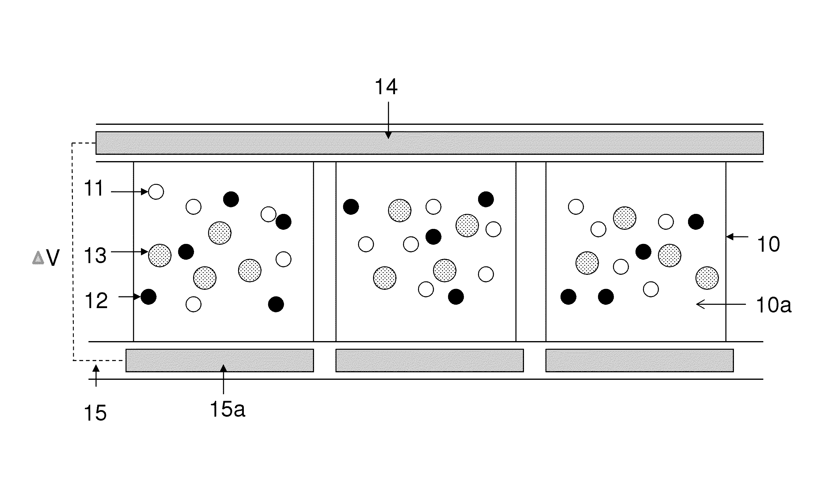
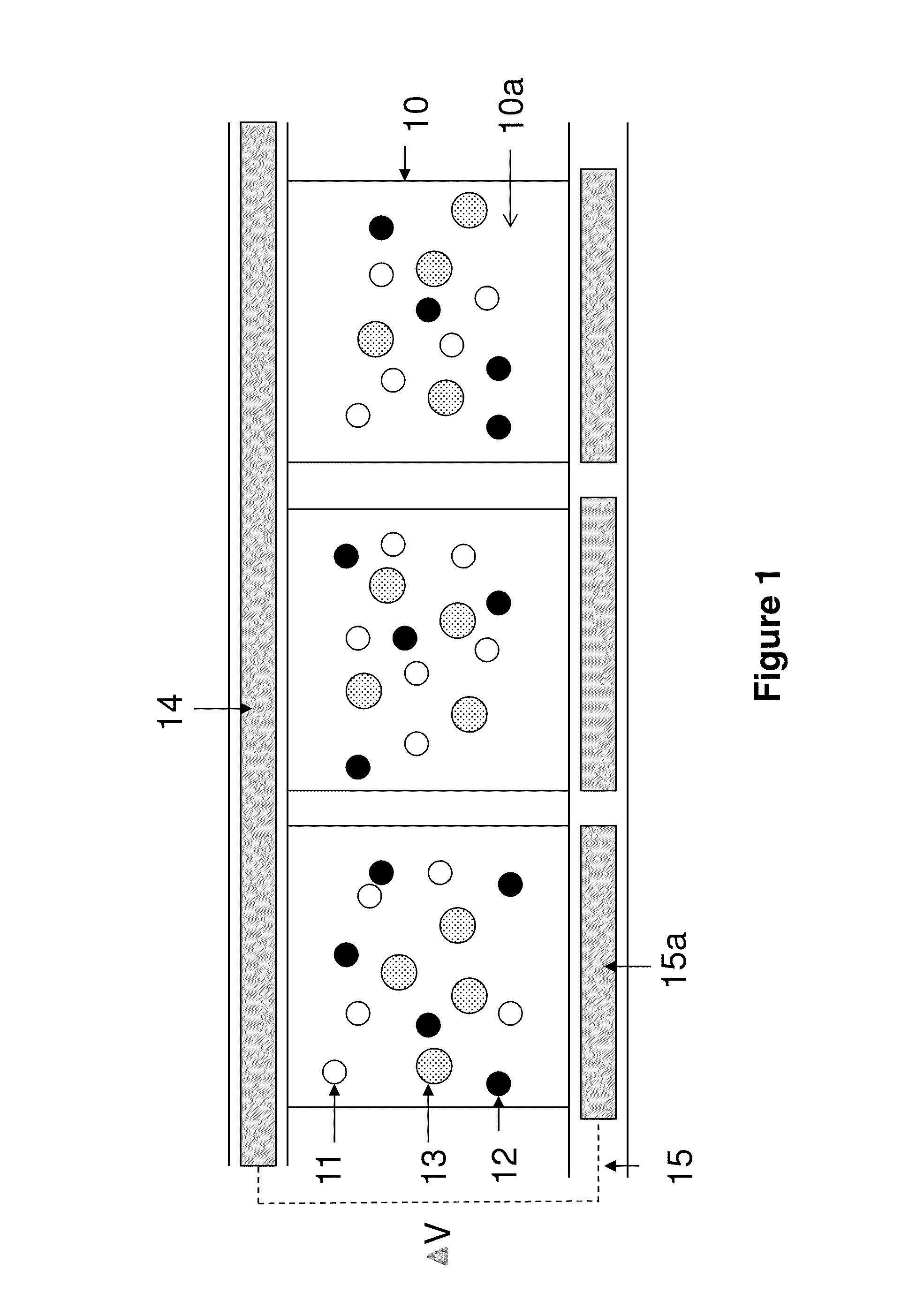
[0061]It is also possible to have the colored particles to have a threshold voltage, as shown in FIGS. 4(a)-4(c). In this case, the colored particles (43) would not move to the viewing side if an applied voltage potential difference is 5V or lower.

[0062]The black pigment particles (42) are negatively charged while the colored pigment particles (43) are positively charged, and both types of the pigment particles are smaller than the white particles (41).

[0063]The white particles (41) carry the same charge polarity as the colored particles which have the threshold voltage, but are slightly charged. The term “slightly charged” is as defined in Example 1(a) above. As a result, the colored particles move faster than the white particles (41), when an applied voltage potential is higher than the threshold voltage of the colored particles because of the stronger charge intensity they carry.

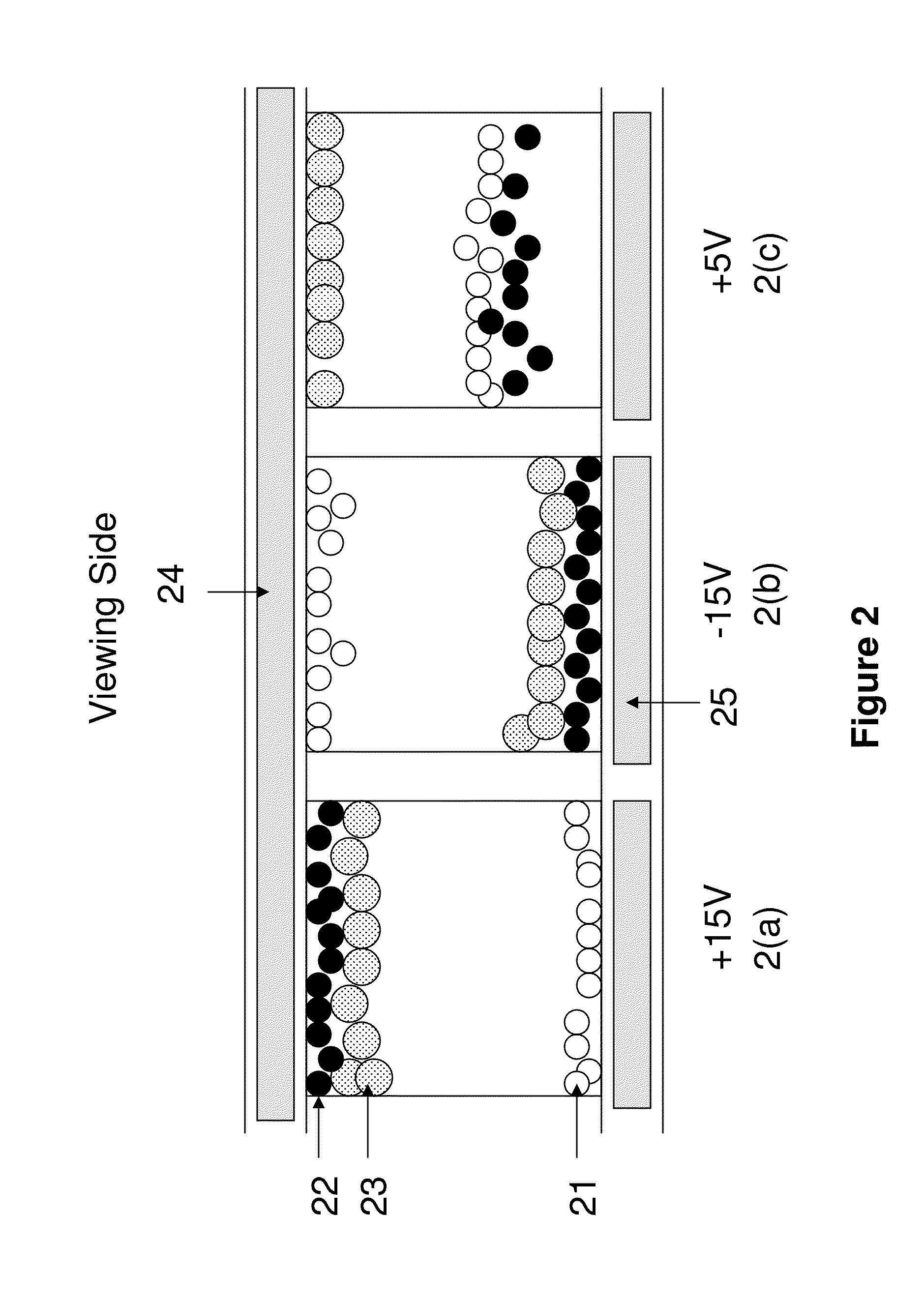
[0064]In FIG. 4a, the applied voltage potential is +15V. In this case, the black particles...

example 2

[0072]This example is shown in FIGS. 5(a)-5(c). It is assumed that the charge intensity of the black particles (52) is twice the charge intensity of the white particles (51) and therefore the black particles move twice as fast as the white particles. The colored particles (53) have a charge intensity which is less than 50% the charge intensity of the white particles.

[0073]Therefore if it takes a driving time, t, for the black particles to travel the distance between the common electrode and a pixel electrode (“d”), it would then take 2 t for the white particles and at least 4 t for the colored particles, to travel the same distance, d.

[0074]In addition, the black particles are positively charged and the white particles are negatively charged. The colored particles carry the same charge polarity as the particles having the highest intensity, that is, the black particles in this case.

[0075]In FIG. 5a, when a negative voltage potential is applied to the common electrode (54) and the pi...


PUM

PropertyMeasurementUnit
dielectric constantaaaaaaaaaa
sizesaaaaaaaaaa

Abstract

The present invention provides a solution for a highlight or multicolor display device, in which each display cell can display high quality color states. More specifically, an electrophoretic fluid is provided which comprises three types of pigment particles, having different levels of size, threshold voltage or charge intensity.

Description

FIELD OF THE INVENTION[0001]The present invention is directed to a color display device in which each display cell can display high quality color states, and an electrophoretic fluid for such an electrophoretic display.BACKGROUND OF THE INVENTION[0002]In order to achieve a color display, color filters are often used. The most common approach is to add color filters on top of black / white sub-pixels of a pixellated display to display the red, green and blue colors. When a red color is desired, the green and blue sub-pixels are turned to the black state so that the only color displayed is red. When the black state is desired, all three-sub-pixels are turned to the black state. When the white state is desired, the three sub-pixels are turned to red, green and blue, respectively, and as a result, a white state is seen by the viewer.[0003]The biggest disadvantage of such a technique is that since each of the sub-pixels has a reflectance of about one third (⅓) of the desired white state, t...

Claims


Application Information

Patent Timeline
Patent Type & Authority Patents(United States)
IPC IPC(8): G02B26/00G09G3/34G02F1/167G02F1/1685
CPCC09K9/00G02F1/167G02F2001/1678G02F1/1685
Inventor WANG, MINGLI, YUDU, HUIZHANG, XIAOJIA
Owner E INK CORPORATION
Why Eureka
Try Eureka