Shoe holder system for bicycle saddle

a bicycle saddle and shoe holder technology, applied in the field of bicycle accessories, can solve the problems of prone to breakage of the muderlak system, inability to accommodate or even consider a bracket for securing athletic shoes, and bulky receiver units, etc., to facilitate the modern trend of illegal triathlon

Inactive Publication Date: 2014-05-13
ANGELI ALDO +1
View PDF11 Cites 4 Cited by
  • Summary
  • Abstract
  • Description
  • Claims
  • Application Information

AI Technical Summary

Benefits of technology

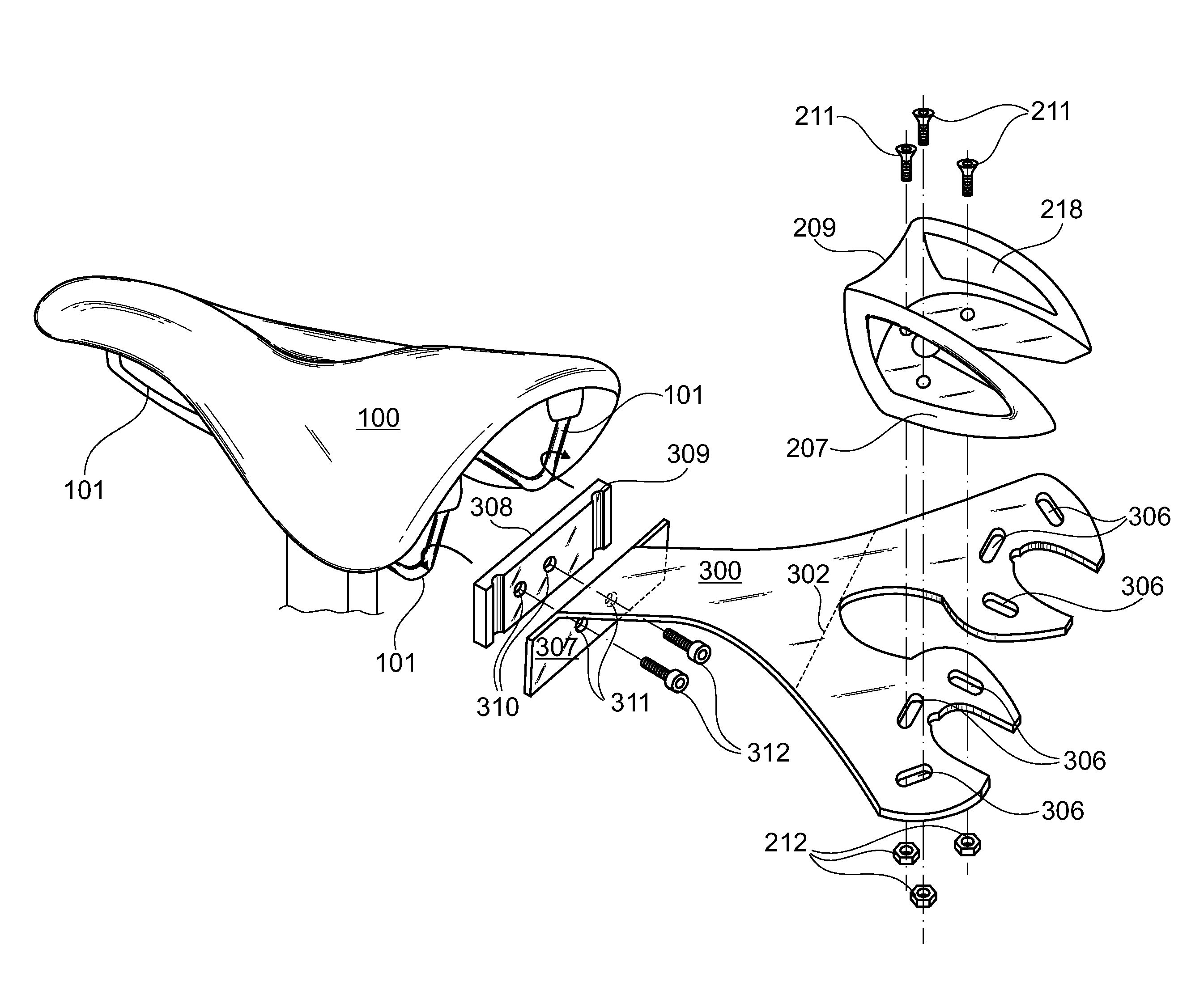
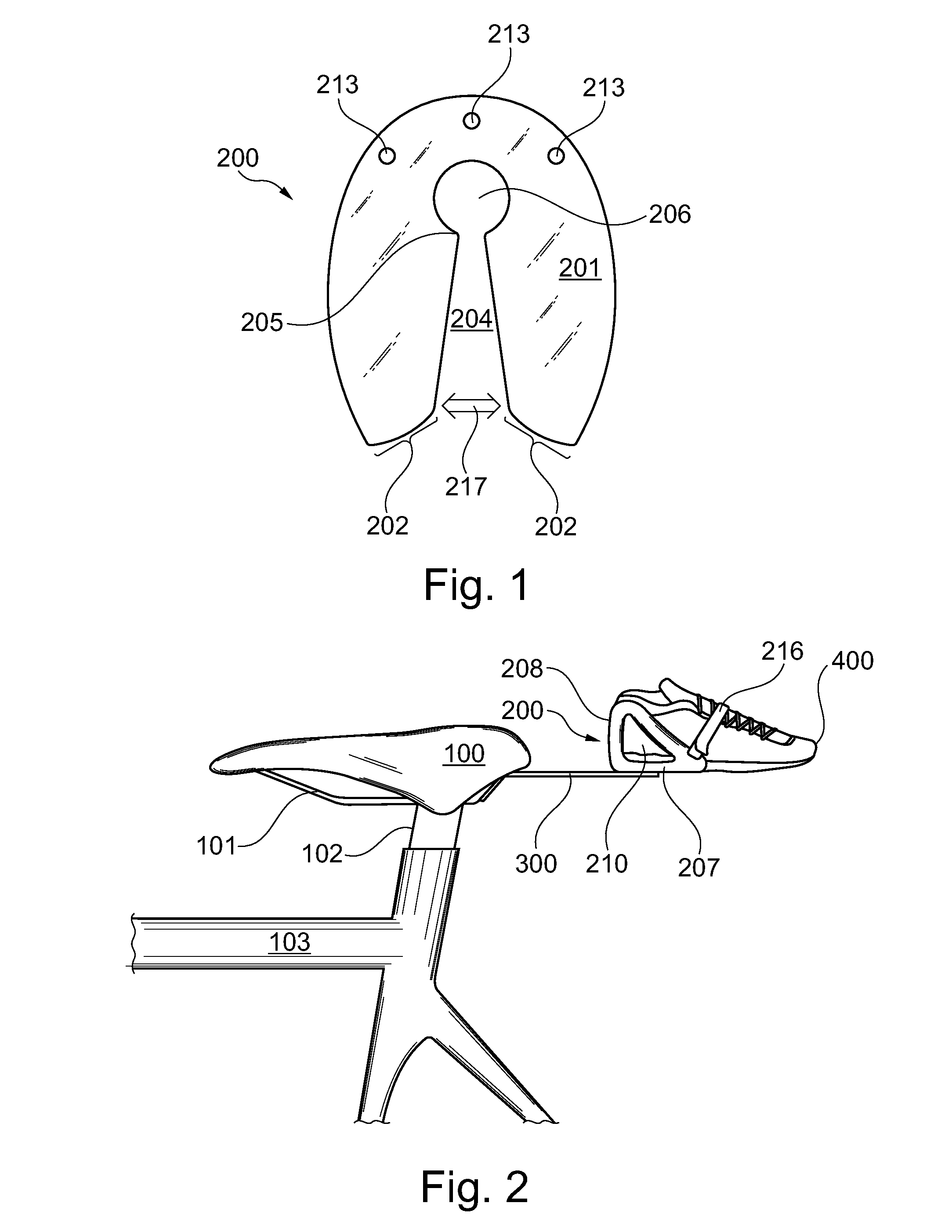
[0010]The present invention overcomes shortfalls in the related art by presenting an unobvious and unique combination, configuration and use of both flexible and inflexible compounds and assemblies to conveniently attach a pair of running shoes to the rear of a bicycle seat. Unlike the known prior art, embodiments of the present invention do not require any permanent modifications to a bicycle saddle. Unlike the multi-walled structure of Schopf, the present invention does not encase items, but instead uses a minimalist flexible cup system to secure athletic items.
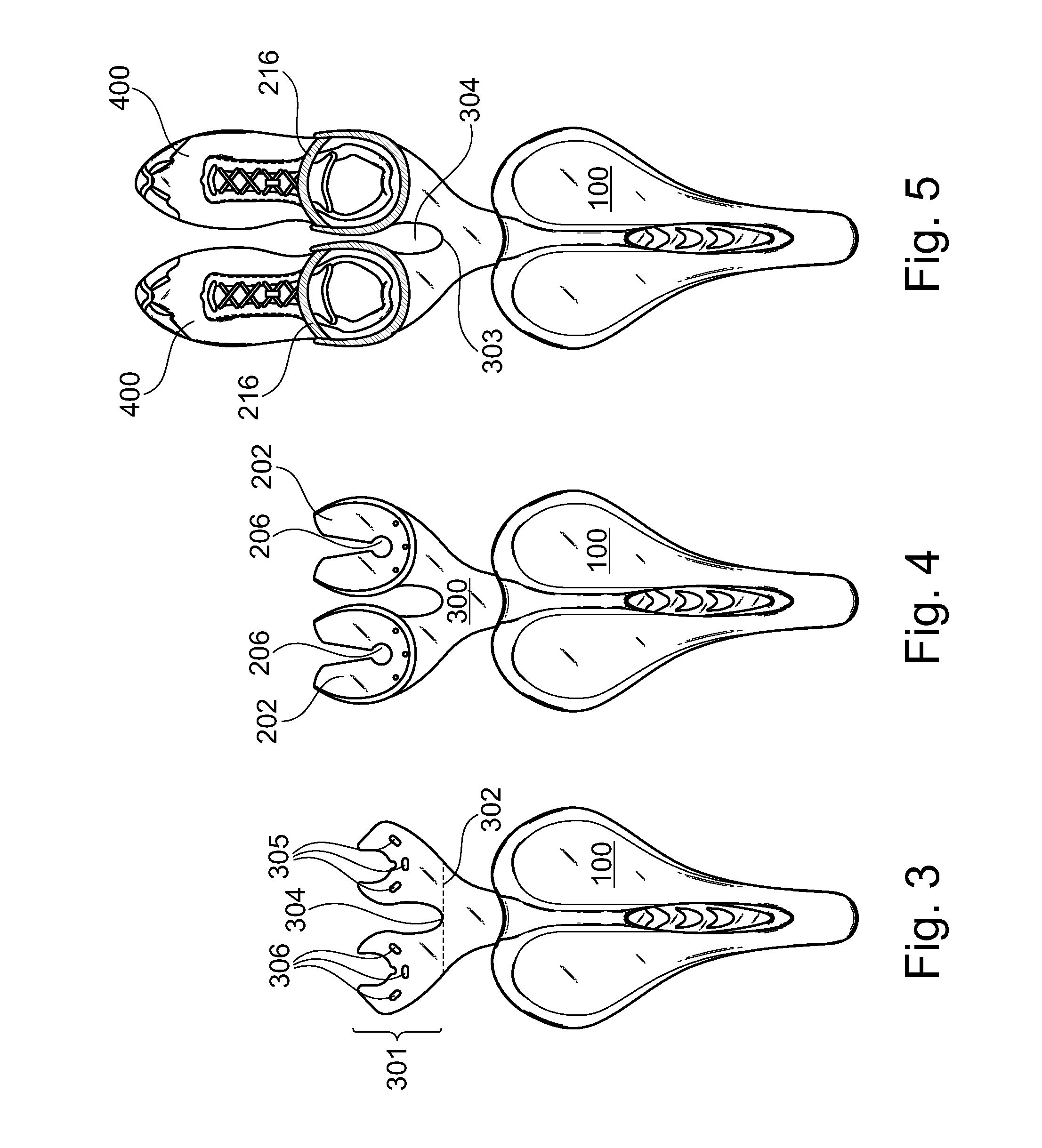
[0011]Embodiments of the invention include means and methods of attaching running shoes or other types of shoes by use of a flexible cupped shoe holder having a unique and artful design as shown and described herein. Embodiments of the disclosed shoe holders feature an elastic side portions with key hole floors, allowing shoe heels to be rigidly mounted in one motion and with one hand. As the heel of a shoe is inserted into the open section of a shoe holder, the sides of the shoe holder temporarily expand to accept the shoe. Upon full insertion, the sides of the shoe holder press inwardly, securing the shoe. The key hole design of the shoe floor facilitate the movement of the shoe holder sides.
[0013]The rear wall section of the shoe holder sometimes has an upper arch that may allow for an inward flexing to further secure the shoe and to facilitate ingress and egress of the shoe.
[0015]The middle section of the arm bracket features a center key hole area and a neck section that attaches to an arm bracket section. The arm bracket section may be rigidly attached to the neck section or may be hingedly attached to the neck section. In yet another embodiment, the neck section is attached to the arm bracket section by means that allow for a quick or tool less detachment of the neck section from the arm bracket section.
[0018]Embodiments of the disclosed invention facilitate the modern trend of “illegal triathlons” wherein a participant may ride their bicycle to an unmanned venue, dismount from their bicycle, remove their running shoes from the shoe holders, run a course, return to their bicycle, replace their running shoes into the shoe holders, and then ride their bicycles to another location. The ability of a triathlon athlete to transport their own running shoes encourages more free-form training and opens up new course possibilities to organized triathlon events.

Problems solved by technology

The bracket of Trimble fails to accommodate or even contemplate a bracket for securing athletic shoes.
Muderlak requires the use of a bulky receiver unit.
The system of Muderlak is prone to breakage as users press upon a disengage pawl.
Bigolin is not well suited for current bicycle saddles as the Bigolin system requires at least one component to be integrally and monolithically formed into the body of the saddle.
The Bigolin system, while stylish, requires specialized moldings and saddle construction.
Thus, the Bigolin system will not adapt to standard bicycle saddles.
The Schopf system requires a rider to manipulate a latch system to gain access to stored goods, thus placing a rider at risk of crashing.
The known prior art fails to provide either means or methods of conveniently securing a pair of running shoes behind a bicycle saddle.

Method used


Image

  • Shoe holder system for bicycle saddle
  • Shoe holder system for bicycle saddle
  • Shoe holder system for bicycle saddle

Examples


Embodiment Construction

[0078]The following detailed description is directed to certain specific embodiments of the invention. However, the invention can be embodied in a multitude of different ways as defined and covered by the claims and their equivalents. In this description, reference is made to the drawings wherein like parts are designated with like numerals throughout.

[0079]Unless otherwise noted in this specification or in the claims, all of the terms used in the specification and the claims will have the meanings normally ascribed to these terms by workers in the art.

[0080]Unless the context clearly requires otherwise, throughout the description and the claims, the words “comprise,”“comprising” and the like are to be construed in an inclusive sense as opposed to an exclusive or exhaustive sense; that is to say, in a sense of “including, but not limited to.” Words using the singular or plural number also include the plural or singular number, respectively. Additionally, the words “herein,”“above,”“...


PUM

PropertyMeasurementUnit
angleaaaaaaaaaa
widthaaaaaaaaaa
areaaaaaaaaaaa

Abstract

Embodiments of the disclosed systems are useful to participants in triathlons who wish to transport their own running shoes while bicycling. Athletic shoes are transported behind a bicycle saddle by use of an arm bracket 300 attaching to saddle rails 101. The arm bracket comprises an attachment section 307, a neck section 317 and two antler 301 styled sections. Each antler section includes an outer prong area 313 and an inner prong area 314. A shoe holder 200 attaches to each antler section wherein voids within the shoe holders match the voids found within the arm bracket components. The side components of the shoe holders assist in preventing rotational movement of a shoe. Each shoe holder further comprises a rear retainer section 208 having an upper arch edge 209, useful in allowing the shoe holder to flex inwardly or outwardly to facilitate the ingress or egress of a shoe.

Description

BACKGROUND OF THE INVENTION[0001](1) Field of the Invention[0002]The invention generally relates to bicycle accessories. More particularly, the invention relates to means and methods of attaching athletic shoes to a bicycle saddle.[0003](2) Description of the Related Art[0004]U.S. Pat. No. 4,957,227 by Trimble discloses support rails to attach a water bottle to the rear section of a bicycle saddle. The bracket of Trimble fails to accommodate or even contemplate a bracket for securing athletic shoes.[0005]U.S. Pat. No. 5,496,089 by Muderlak discloses a complex clip attachment assembly that integrates into a bicycle seat. Muderlak requires the use of a bulky receiver unit. The system of Muderlak is prone to breakage as users press upon a disengage pawl.[0006]U.S. Pat. No. 7,264,308 by Bigolin discloses a quick release system to secure a bracket behind a bicycle saddle. Bigolin is not well suited for current bicycle saddles as the Bigolin system requires at least one component to be in...

Claims


Application Information

Patent Timeline
Patent Type & Authority Patents(United States)
IPC IPC(8): B62J9/00
CPCB23P11/00B62J11/00B62J9/006B62J1/28B62J9/26Y10T29/49959
Inventor ANGELI, ALDOANGELI, MICHELE
Owner ANGELI ALDO
Why Eureka
Try Eureka