
Sensor system for saccharides

a technology of saccharide and sensor system, which is applied in the field of fluorescence sensor molecules, can solve the problems of imposing strict limitations on the type of fluorophore, its size and conformation, and serious shortcomings, and achieves significant limitations on the type, size and conformation of analytes that can specifically bind to the disclosed fluorescent compounds

Active Publication Date: 2008-04-15
BAXTER INT INC +1
View PDF23 Cites 25 Cited by
  • Summary
  • Abstract
  • Description
  • Claims
  • Application Information

AI Technical Summary

Benefits of technology

[0018]Accordingly, it is an object of the present invention to provide a fluorescent sensor, particularly PET-type sensor, with a modular structure, which allows independent selection of fluorescent and binding groups. It is also an object of the present invention to provide a fluorescent sensor that can be easily adapted for specific binding to a broad range of analytes. It is a further object of the present invention to provide a fluorescent sensor that can be used in both homogeneous and heterogeneous binding assay formats and can be easily attached to solid surfaces. Finally, it is an object of the present invention to provide convenient methods of making and using the fluorescent sensors.
[0039]The modular fluorescence sensor of the present invention has been found to provide a number of advantages. The modular structure of the sensor allows a convenient replacement of its functional parts to fit analytes within a broad range of structures, binding affinities, and solubilities. The anchor site and the asymmetrical structure of the instant sensor permit a convenient attachment of the sensor to a variety of solid substrates, as required in heterogenic assay formats. Also, the fluorescent sensor of this invention couples the signal generation to the analyte binding and thereby localizes the measurement of an analyte. Consequently, the sensor is well suited for applications in particle-based assays and flow cytometry. Finally, in the present invention, a special spacer group is used to provide the desired intramolecular distance between analyte-binding groups, which governs the analyte selectivity. The conventional PET-type sensors, on the other hand, utilize a fluorophore as a spacer, which puts stringent limitations on the type of fluorophore that can be used. On the contrary, in the present invention, the fluorophore may be selected without limitations to its size or conformation.

Problems solved by technology

While an application of above-described fluorescent sensors in biochemical assays and clinical tests provide certain advantages over earlier enzyme-based in vitro methods, it, nevertheless, suffers from serious shortcomings.
Because the fluorophore is used as a spacer to separate the saccharide binding groups and to provide desired analyte selectivity, strict limitations on the type of the fluorophore, its size and conformation are imposed.
For the same reason, there are also significant limitations on the type, size, and conformation of analyte that can specifically bind to the disclosed fluorescent compounds to produce a detectable signal.
Furthermore, although the referenced art suggests using the PET-type fluorescent compounds in a heterogeneous assay format, no means for attaching the compound to a solid support are provided.
Again, such attachment would be particularly difficult in view of the strict limitations imposed on the conformation and structure of the fluorescent molecule.

Method used


Image

  • Sensor system for saccharides
  • Sensor system for saccharides
  • Sensor system for saccharides

Examples


example i

[0114]The fluorescent sensor of the formula (5) was prepared as described in detail below.

Preparation of N-benzyl-hexane-1,6-diamine

[0115]A solution of hexamethlene-1,6-diamine (17.15 g, 148 mmol) and benzaldehyde (3.0 ml, 29.5 mmol) in tetrahydrofuran (THF) (300 ml) and ethanol (75 ml) was stirred at room temperature for 24 hours under a nitrogen atmosphere. The solvent was removed and the oil was dried under vacuum. The dried residue was dissolved in THF (100 ml) and sodium borohydride (5.58 g, 148 mmol) was added to the solution. The solution was stirred at room temperature for 7 hours under nitrogen atmosphere. Methanol and water were added to the solution and the solvents were removed under vacuum. The obtained oil was dissolved in chloroform, and washed with water. The solution was dried over magnesium sulphate and the solvent was then removed under vacuum to give a colorless oil (4.49 g, 74%). 1H NMR (CDCl3) δ / ppm 1.1-1.5 (8H, m, (CH2)4), 2.55 (2H, t, NHCH2), 2.65 (2H, t, ArC...

example ii

[0119]A relative fluorescent intensity of the sensor of formula (5), as prepared in EXAMPLE I, was measured in 52.1 wt % methanol and phosphate buffer (pH 8.21) with various D-glucose concentrations (FIG. 3). Phosphate buffer was prepared as described in D. D. Perrin, and B. Dempsey, Buffers for pH and Metal Ion Control, Chapman and Hall, London, 1974. The fluorescence spectra were recorded as increasing amounts of D-glucose were added to the solution. The mixture solutions were measured excitation at 342 nm. The fluorescent intensity was found to correlate with total D-glucose concentration in the solution.

example iii

Preparation of Beads with Glucose Binding Sensor (Prospective Example)

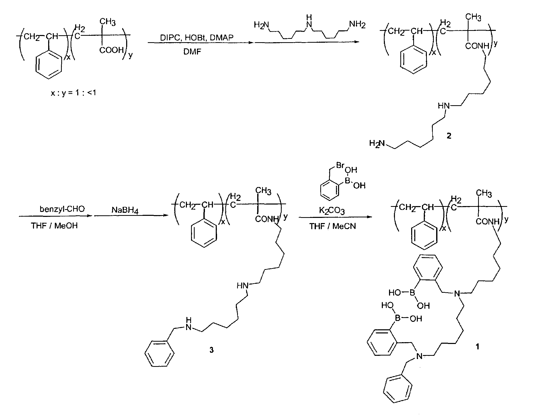
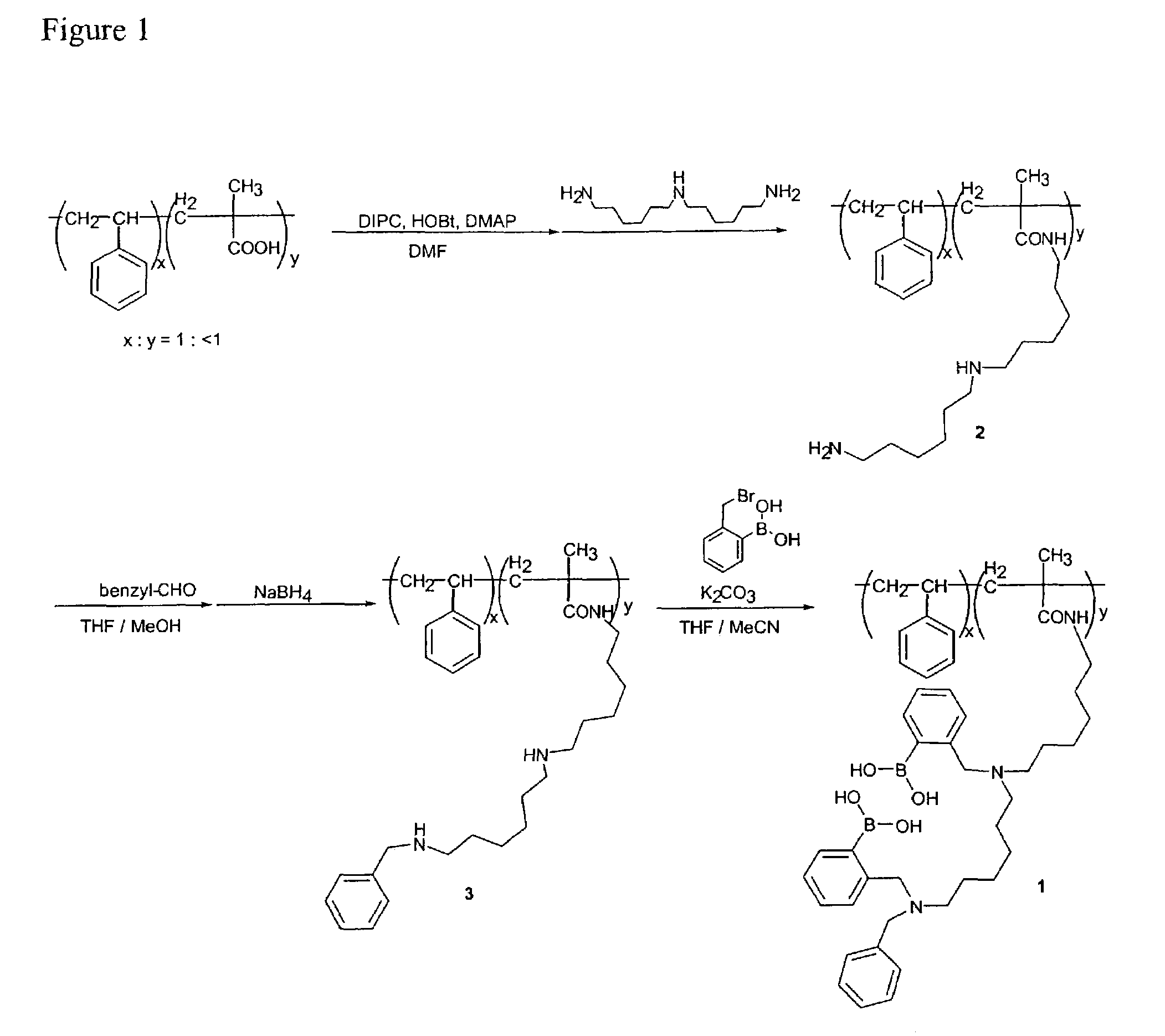
[0120]The preparation of a glucose binding sensor to beads is illustrated in detail in FIG. 1. The beads are 5.6 micrometer diameter poly (styrene / 5.5% divinyl benzene / 5% methacrylic acid), available from Bangs, Laboratories, Inc. of Fishers, Ind. Compound 2 illustrated in FIG. 1 is prepared by stirring a suspension of cross-linked carboxylate modified polymer beads (200 mg), 1,3-diisopropylcarbodiimide (DIPC) (170 mg), 1-hydroxy-1H-benzotriazol (HOBt) (200 mg,), 4-N,N-dimethylaminopyridine (DMAP) (8 mg) in N,N-dimethylformamide (DMF) (5 ml) on an ice bath under nitrogen atmosphere for 30 minutes. Next, bis(hexamethylene) triamine (1.0 g) is added to the solution and stirred at room temperature for 1 day. This reaction mixture is poured into tetrahydrofuran (THF) and stirred for 1 h at room temperature. The mixture is centrifuged to settle the beads, the supernatant was decanted, and the beads are resuspend in met...


PUM

PropertyMeasurementUnit
Nanoscale particle sizeaaaaaaaaaa
Ratioaaaaaaaaaa

Abstract

An analytical system for detecting a saccharide is provided. The analytical system includes a saccharide sensor attached to a solid substrate and having the formula:Where Z is selected from the group consisting of hydrogen, alkyl groups, an aryl; N is a nitrogen atom; Bd1 and Bd2 are independently selected binding groups, wherein the binding groups are capable of binding an saccharide; Sp is a spacer; An is an anchor group for attaching the sensor to solid substrate, including a bead; and n=1 or 2, m=1 or 2, y=1 or 2, and p is an integer. In one embodiment the saccharide sensor preferentially detects glucose. The invention further provides beads having the saccharide sensor attached thereto and methods of detecting glucose using the system.

Description

CROSS REFERENCE TO RELATED APPLICATION[0001]This application is related to U.S. Pat. No. 6,387,672, the contents of which are hereby incorporated by reference in their entirety.BACKGROUND OF THE INVENTION[0002]The following description provides a summary of information relevant to the present invention and is not a concession that any of the information provided or publications referenced herein is prior art to the presently claimed invention.[0003]1. Area of the Art[0004]The invention relates generally to fluorescence sensor molecules and specifically to a new group of modular fluorescence sensor molecules.[0005]2. Description of the Prior Art[0006]Numerous assay methods have been developed for the detection and quantitative determination of analytes contained in biochemical samples. A substantial portion of the currently used assay methods relies on specific binding reactions between analytes and assay reagents. The analytes may be large complex molecules, such as proteins, viruse...

Claims


Application Information

Patent Timeline
IPC IPC(8): G01N21/76C12Q1/68G01N33/00G01N33/53G01N33/533G01N33/543G01N33/66
CPCG01N33/5308G01N33/533G01N33/66G01N33/54346Y10T436/143333
Inventor BELL, MICHAEL L.JAMES, TONY D.ARIMORI, SUSUMU
Owner BAXTER INT INC
Learn More