
Connected fastener assembly

a fastener and connecting technology, applied in the direction of threaded fasteners, screwdrivers, applications, etc., can solve the problems of inability to wound into a coil, high risk of hitting and injuring human bodies, and the production of garbage, so as to improve the performance of guiding the fastener at the time of driving, the density of the fastener becomes low, and the strength of the connecting section is very large

Active Publication Date: 2014-05-13
MAX CO LTD
View PDF38 Cites 2 Cited by
  • Summary
  • Abstract
  • Description
  • Claims
  • Application Information

AI Technical Summary

Benefits of technology

The invention is a fastener assembly that allows for secure and proper feeding of fasteners in a safe and efficient manner. The assembly includes a connecting section that is curved or bent to offset the center portion, which results in improved efficiency and performance. The structure also allows for easy winding of the assembly into a coil for storage and transportation. The assembly has a tubular retaining section that can hold the fastener securely, and a connecting section that is strong and durable. The assembly also includes a cylindrical portion that allows for easy fitting of the fastener into a driving tool. Overall, the invention provides a fastener assembly with improved efficiency, safety, and performance.

Problems solved by technology

However, the connected fastener assembly in which multiple fasteners are integrally connected to a straight connecting band made of a synthetic resin so as to be formed into a stick shape has a problem of being unable to be wound into a coil.
In addition, in the case of the connected fastener assembly according to the wire connecting method, wires are scattered at the time of driving, whereby there is a danger of striking and injuring human bodies and garbage is produced.
When such nails are driven into high-strength concrete or the like, the nails are likely to buckle or fracture.
Moreover, if the connected fastener assembly wound into a coil is dropped to the floor or ground inadvertently when the connected fastener assembly is loaded into the magazine of a fastener driving tool, the exterior of the coil may be deformed.
If the exterior is deformed, it is difficult to restore the coil into its original shape.
In this case, there is a danger that the finger is injured by the tip ends of the wires.
Hence, the strength of the nose section lowers, and the connecting band becomes garbage and must be thrown away.
However, if bent at an acute angle, the connecting sections are subjected to large stress, thereby being lowered in strength and whitened.
As a result, the connecting sections may be broken owing to vibration or impact at the time of driving, thereby causing improper feeding.
However, the pitch between the fasteners increases, and there is a problem that the number of fasteners to be connected is reduced.
In addition, if the connecting sections are disposed along the center line of the connecting band, when the connected fastener assembly is loaded into the magazine of a fastener driving tool, the tip end of the feeding pawl of the tool interferes with the connecting section and cannot engage the center of the retaining section of the connecting band, and improper feeding may occur.

Method used


Image

  • Connected fastener assembly
  • Connected fastener assembly
  • Connected fastener assembly

Examples


Embodiment Construction

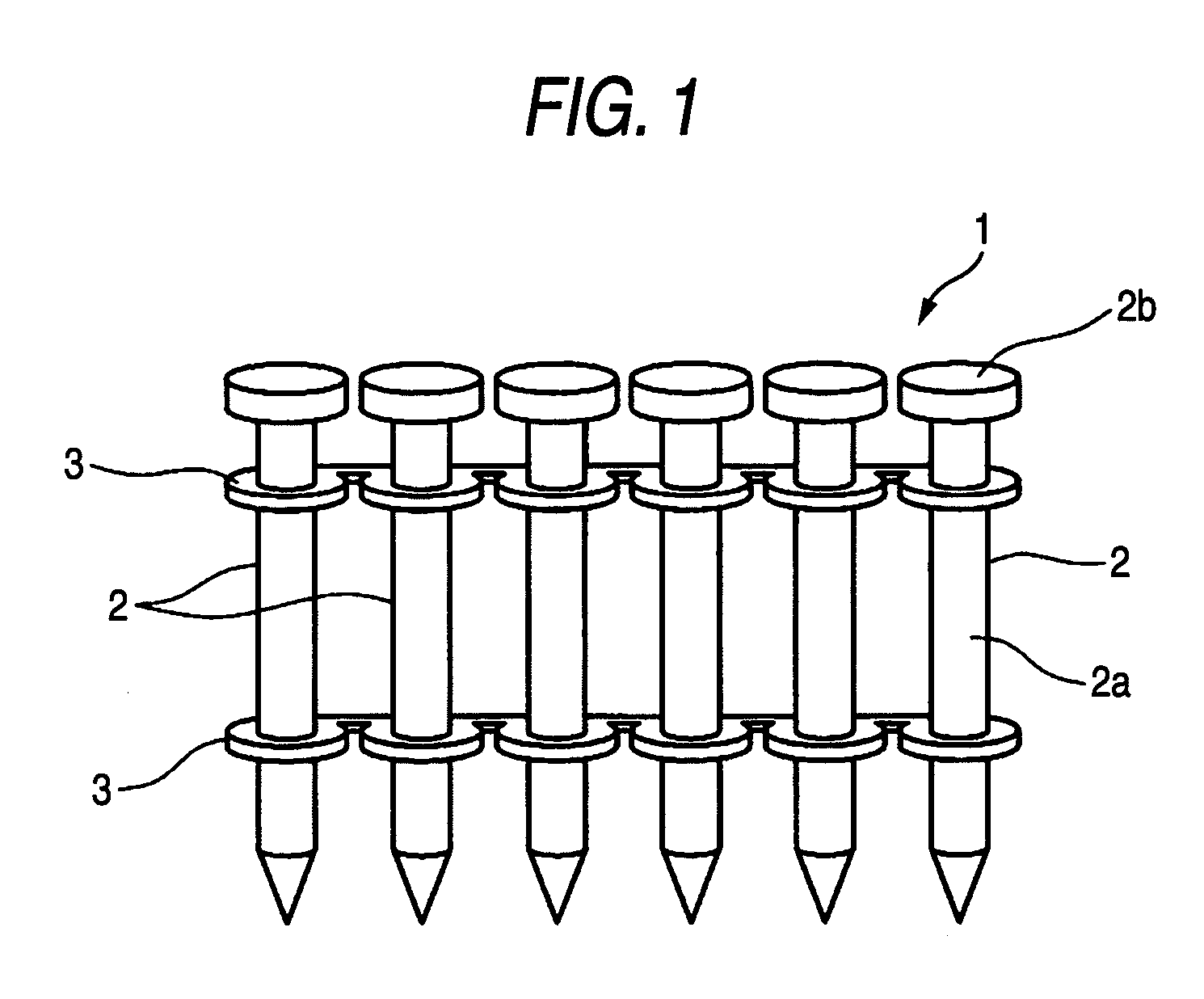
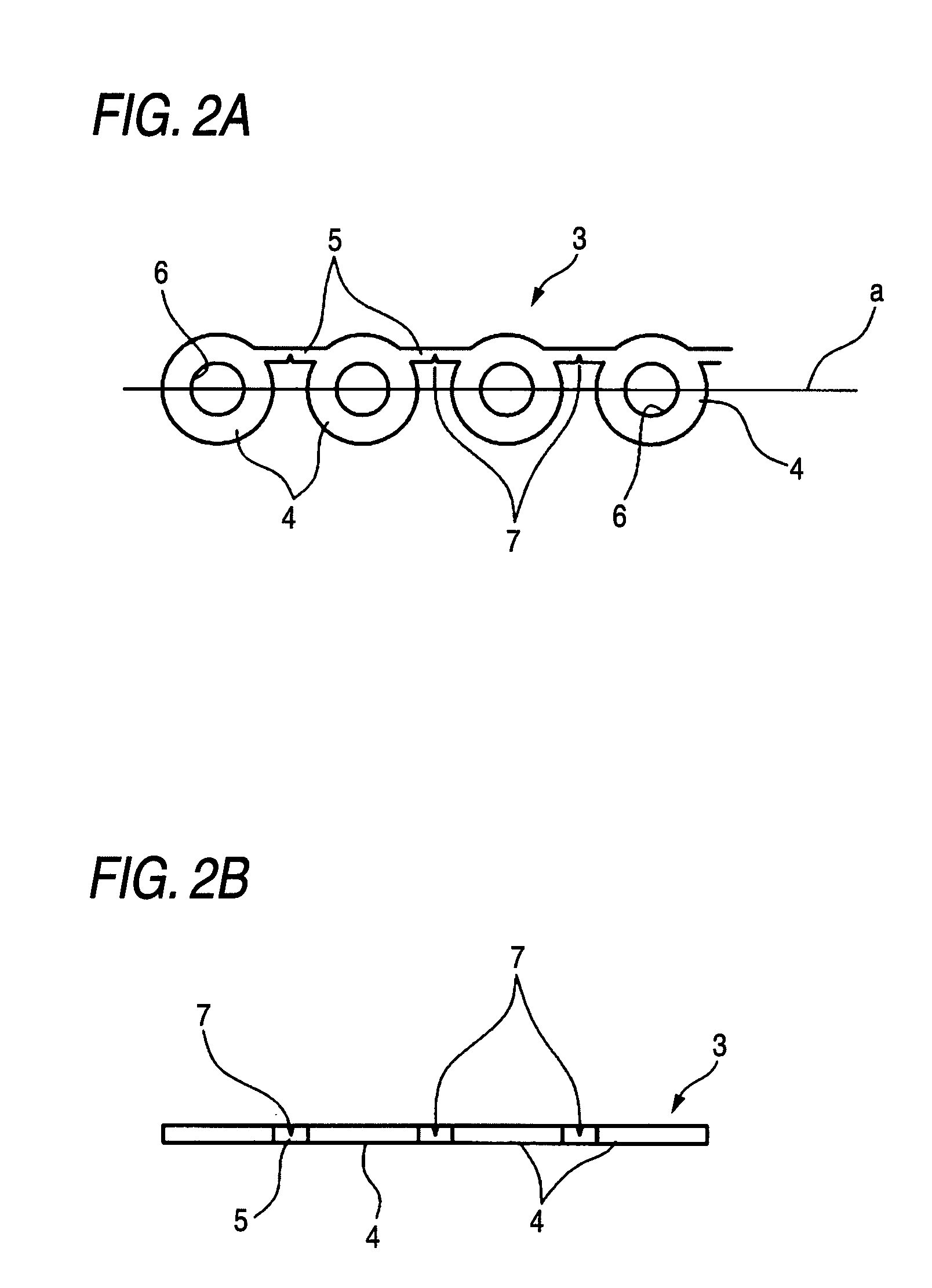
[0054]1 connected fastener assembly[0055]2 fastener[0056]3 connecting band[0057]4 retaining section[0058]5 connecting section[0059]7 notch

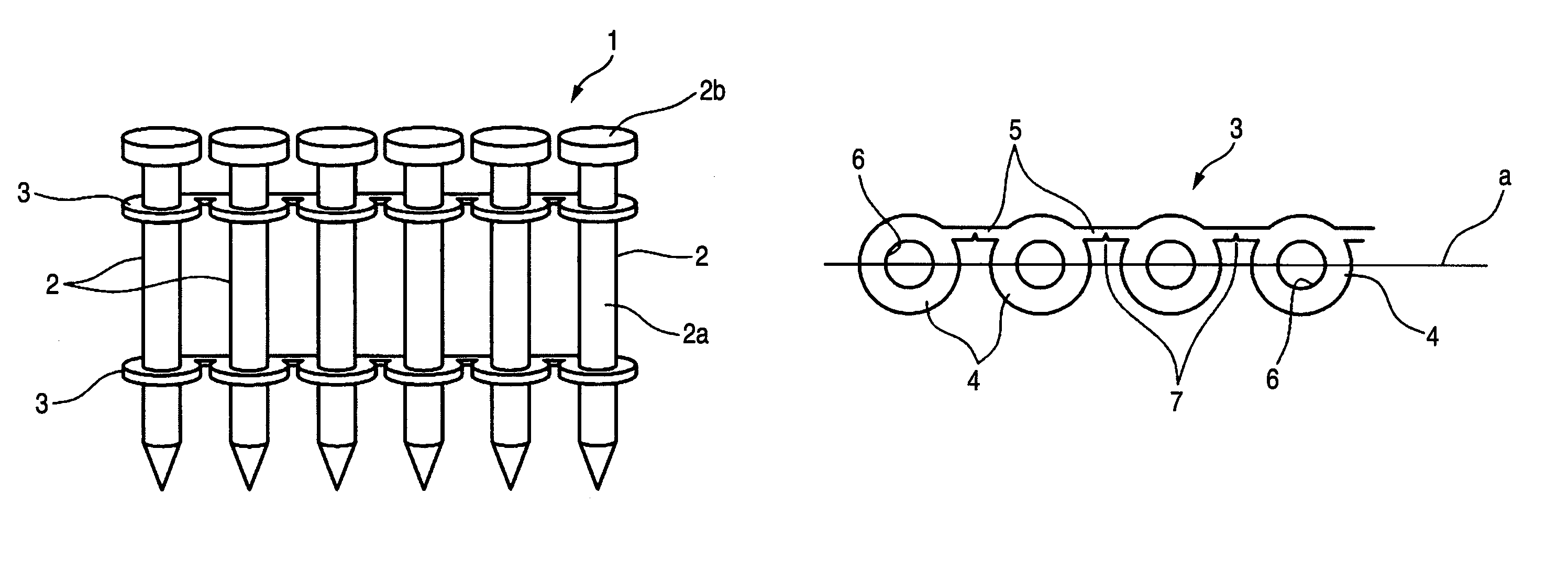
[0060]In FIG. 1, numeral 1 designates a connected fastener assembly. This connected fastener assembly 1 is formed by connecting the shaft sections 2a of multiple fasteners 2 (concrete pins) using connecting bands 3. The connecting band 3 is obtained by press molding a band-shaped connecting sheet made of a synthetic resin, such as polyethylene, wherein a retaining section 4 for allowing the shaft section 2a of the fastener 2 to be inserted and a connecting section 5 for connecting the adjacent retaining sections 4 are formed continuously as shown in FIG. 2A.

[0061]The retaining section 4 is circular in outer shape and is formed to have the same size as that of the head section 2b of the fastener 2. A fitting hole 6 for allowing the shaft section 2a of the fastener 2 to be fitted therein is formed at the center portion of the retaining section 4.

[00...


PUM


Abstract

In a connected fastener assembly, the shaft sections of multiple fasteners are connected using a connecting band made of a synthetic resin. Retaining sections for allowing the shaft sections of the fasteners to be inserted therein and connecting sections for connecting the adjacent retaining sections are formed continuously. The connecting sections are offset from the center line “a” connecting the centers of the adjacent fasteners (retaining sections).

Description

[0001]This application claims priority under 35 U.S.C. §119 to Japanese Patent Application No. JP2007-288920, filed on Nov. 6, 2008, which is incorporated by reference herein in its entirety.FIELD OF THE INVENTION[0002]The present invention relates to a connected fastener assembly for use in a fastener driving tool powered by pneumatic pressure, fuel gas, etc.BACKGROUND OF THE INVENTION[0003]A fastener driving tool for driving fasteners, such as nails, drive screws, etc. is a tool in which a connected fastener assembly connecting multiple connected fasteners is stored in a magazine and the fasteners are fed to the nose section of the driving tool sequentially beginning with the first fastener so that the fasteners are driven continuously into workpieces.[0004]Such fasteners are used not only to anchor wood to wood, but also to fasten liners or wood to concrete, to secure I-beams to thin steel sheets and to fasten denz glass (a plaster board-like material) to studs.[0005]As methods f...

Claims


Application Information

Patent Timeline
Patent Type & Authority Patents(United States)
IPC IPC(8): F16B15/08
CPCF16B15/08F16B13/00F16B15/00F16B19/00
Inventor NAKAGAWA, YASUSHIYAMAMOTO, HIROKIHOSHINO, TAKAMICHITAKEUCHI, KAZUHISA
Owner MAX CO LTD
Learn More