Air pump

a technology of air pump and air chamber, which is applied in the direction of piston pump, positive displacement liquid engine, liquid fuel engine, etc., can solve the problems of emitted noise to the surroundings, and achieve the effect of reducing the diameter of the hole, and increasing the noise reduction

Active Publication Date: 2014-05-20
NITTO KOHKI CO LTD
View PDF19 Cites 3 Cited by
  • Summary
  • Abstract
  • Description
  • Claims
  • Application Information

AI Technical Summary

Benefits of technology

[0008]An object of the present invention is to provide an air pump in which a housing accommodating a pump unit is not used as a noise reduction device as stated above, but noise reduction means is provided in a suction section of the pump unit itself to further improve the noise reduction effect.
[0010]In this air pump, the casing is formed with a noise reduction wall as stated above, and air to be sucked into the casing is passed through a noise reduction passage formed in the noise reduction wall and introduced into the noise reduction chamber. From the noise reduction chamber, the air is introduced into the casing through a suction port provided to extend through the casing. Accordingly, the path extending from the casing to the outside through the suction port and the noise reduction chamber and further through the noise reduction passage is long so that it is possible to achieve a noise reduction effect to reduce noise leaking out of the casing through the path. The noise reduction chamber can be formed as a wide space, which makes it possible to further increase the noise reduction effect by a combination of the wide-space noise reduction chamber and the narrow noise reduction passage and suction port, which are upstream and downstream, respectively, of the noise reduction chamber. It should be noted that the lid member may be integrally formed with the noise reduction wall.
[0013]In the above-described air pump, a portion of the casing that defines the suction port may be made greater in wall thickness than a portion of the casing surrounding the suction port-defining portion to lengthen the length of the suction port. This is for increasing the noise reduction effect.
[0014]The suction port may comprise a plurality of holes of a small diameter. The smaller the diameter of the holes, the higher the noise reduction effect.

Problems solved by technology

In this regard, vibration noise generated in a drive unit of the pump is transmitted to the outside through an air suction passage and so forth, thus emitting noise to the surroundings.

Method used


Image

  • Air pump
  • Air pump
  • Air pump

Examples


Embodiment Construction

[0028]An embodiment of an air pump according to the present invention will be explained below in detail with reference to the accompanying drawings.

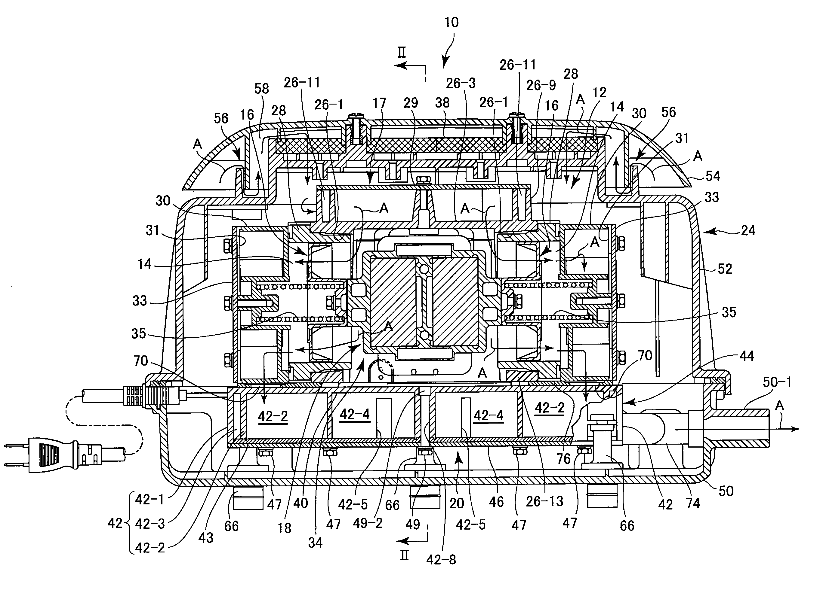
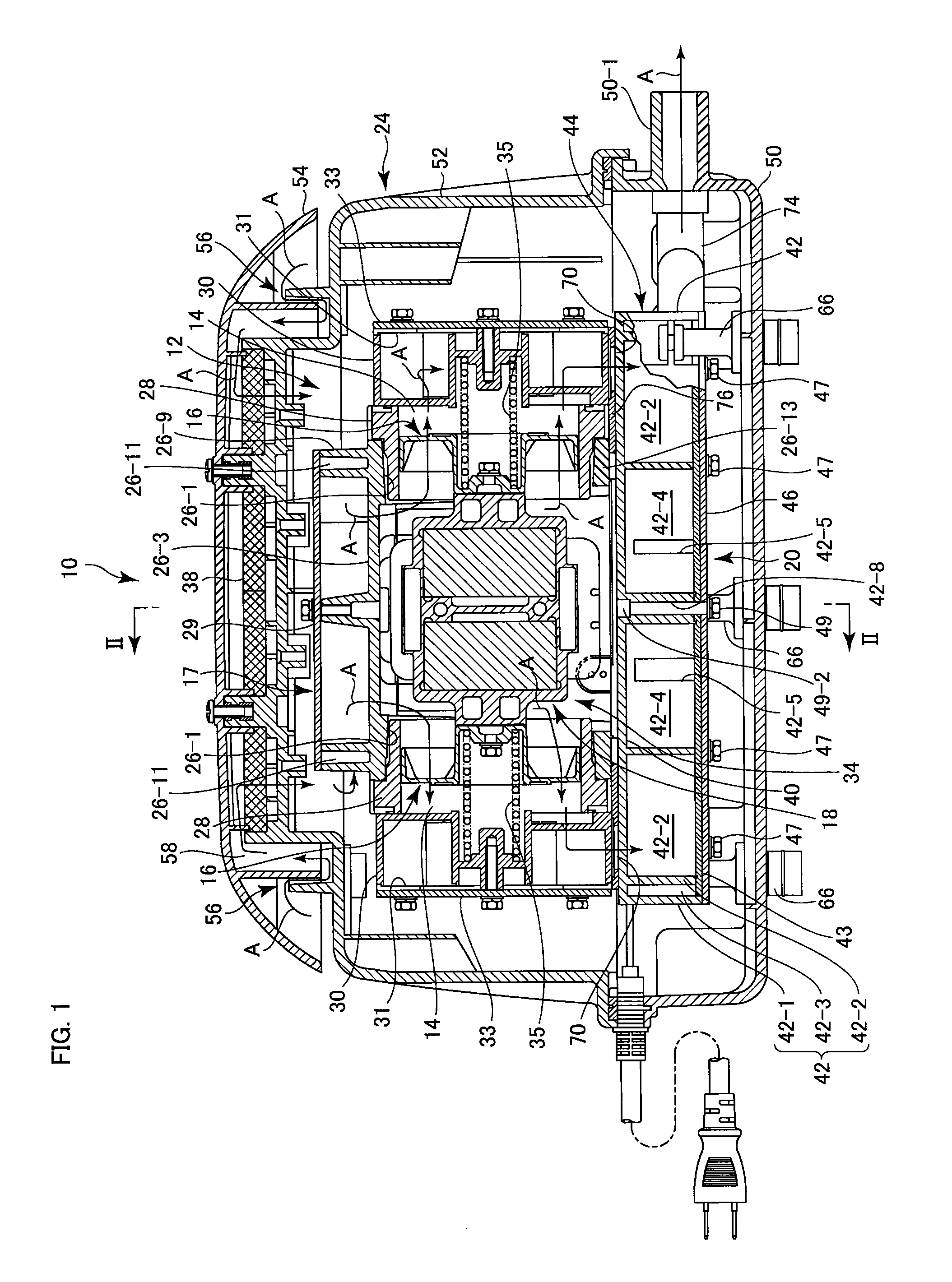
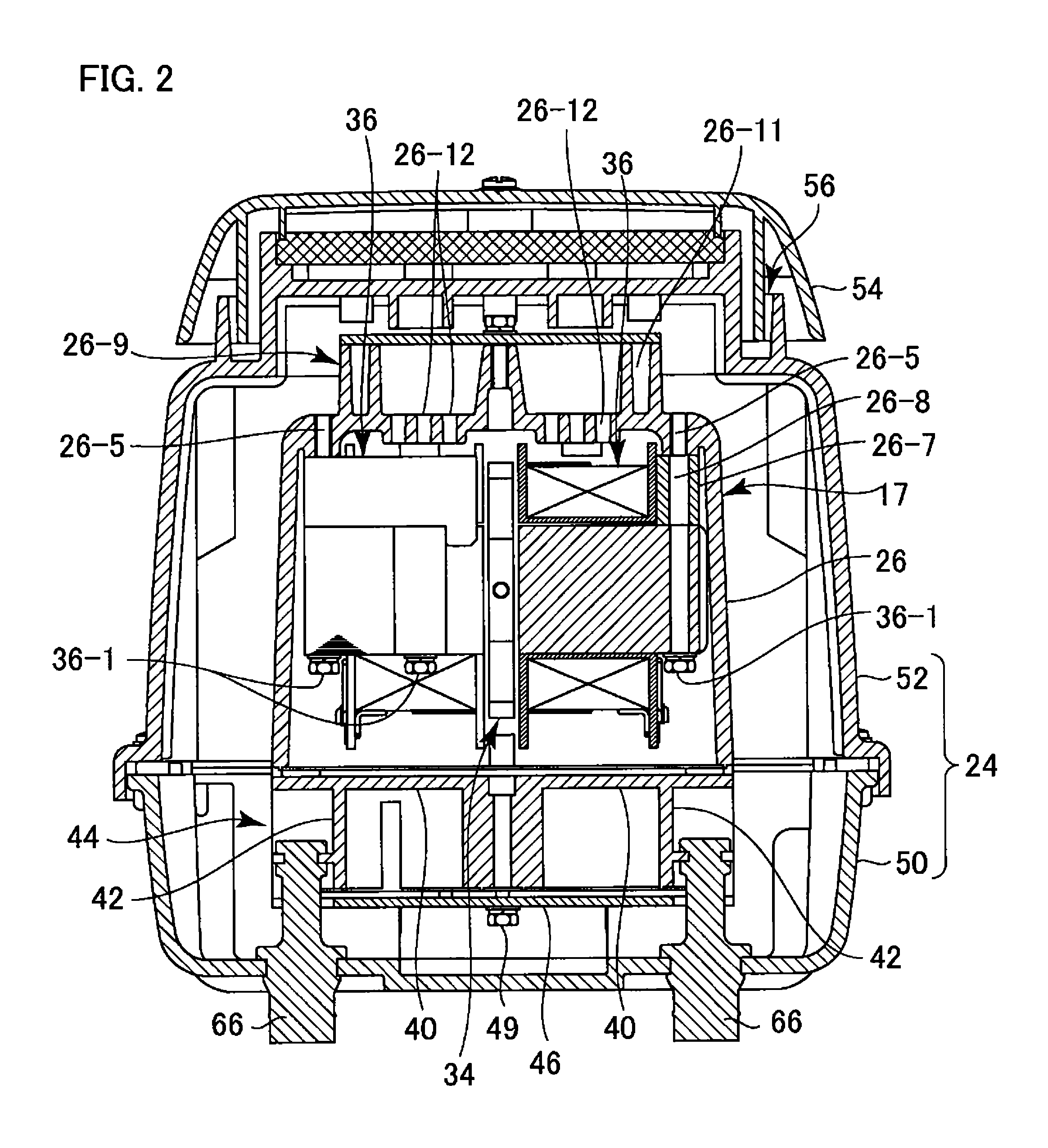
[0029]As illustrated in the figures, an air pump 10 according to the present invention has a pump unit 12 for sucking in and compressing air from the surroundings and an air tank 20 for temporarily storing the compressed air from the pump unit 12 to suppress pulsation caused by reciprocating motion of pistons 16 of the pump unit 12 before discharging the compressed air. The air pump 10 further has a housing 24 accommodating the pump unit 12 and the air tank 20.

[0030]First, these constituent elements and the overall structure will be outlined below.

[0031]First, the pump unit 12 has a casing 17 having a pair of cylinder chambers 14 disposed in bilateral symmetry as seen in FIG. 1 to accommodate the pistons 16, respectively. The pump unit 12 further has an electromagnetic drive unit 18 reciprocating the two pistons 16 in the state of the tw...


PUM


Abstract

There is provided an air pump in which vibration noise generated in a drive unit of the pump is suppressed from being transmitted to the outside through a suction passage. A casing of the air pump has a suction port extending from an outer peripheral surface to inner peripheral surface of the casing, a noise reduction wall annularly formed on the outer peripheral surface of the casing such that the suction port opens in a region of the outer peripheral surface of the casing surrounded by the noise reduction wall, and a lid member closing the opening of the top of the noise reduction wall and cooperating with the noise reduction wall and the outer peripheral surface of the casing to define a noise reduction chamber communicating with the suction port. The noise reduction wall has an elongated noise reduction passage extending circumferentially in the noise reduction wall.

Description

RELATED APPLICATIONS[0001]This application is a continuation of PCT / JP2010 / 051233 filed on Jan. 29, 2010, which claims priority to Japanese Application No. 2009-019860 filed on Jan. 30, 2009. The entire contents of these applications are incorporated herein by reference.BACKGROUND OF THE INVENTION[0002]1. Field of the Invention[0003]The present invention relates to air pumps and, more particularly, to a noise reduction device for use in air pumps.[0004]2. Description of the Related Art[0005]An air pump sucks in air from the surroundings, compresses the air and discharges the compressed air. In this regard, vibration noise generated in a drive unit of the pump is transmitted to the outside through an air suction passage and so forth, thus emitting noise to the surroundings. Accordingly, various noise reduction devices have been developed.[0006]For example, the following patent literature 1 discloses a noise reduction device having a circular cylindrical housing accommodating an air p...

Claims


Application Information

Patent Timeline
Patent Type & Authority Patents(United States)
IPC IPC(8): F04B39/00
CPCF04B35/04F04B39/0038F04B39/0061F04B39/12F04B39/121
Inventor ISHIBASHI, SHIGEMITSUHASHIMOTO, ATSUKI
Owner NITTO KOHKI CO LTD
Why Eureka
Try Eureka