Rotation angle sensor
a technology of rotation angle and sensor, which is applied in the direction of measuring devices, instruments, dynamo-electric machines, etc., can solve the problems of increasing the size of the motor, affecting the detection output, and the resolver is liable to be influenced by the disturbance of electromagnetic noise of the motor, so as to achieve small difference in generated induced voltage and poor s/n ratio
- Summary
- Abstract
- Description
- Claims
- Application Information
AI Technical Summary
Benefits of technology
Problems solved by technology
Method used
Image
Examples
second embodiment
[0162]A second embodiment of an amplitude resolver according to the present invention will be explained below referring to accompanying drawings. The second embodiment is identical to the first embodiment excepting only the shape of a resolver rotor 102. Identical parts are given the same reference signs as those in the first embodiment and their explanations are not repeated herein.
[0163]FIG. 17 is a sectional view of one end part of a resolver-mounted motor 1 (hereinafter, simply referred to as a “motor”). FIG. 18 is an enlarged sectional view showing a part enclosed by a dashed line X1 in FIG. 17. FIG. 19 is an enlarged sectional view showing a part in FIG. 18. As shown in FIG. 17, the motor 1 includes a motor case 2, a motor stator 3 and a motor rotor 4 placed in the motor case 2, and a motor shaft 5 integrally provided in the center of the rotor 4. One end of the shaft 5 slightly protrudes out of the case 2. The case 2 includes a main case body 6A and an end plate 7 fixed to cl...
third embodiment
[0214]A third embodiment of a resolver embodying the present invention will be explained below with reference to accompanying drawings.
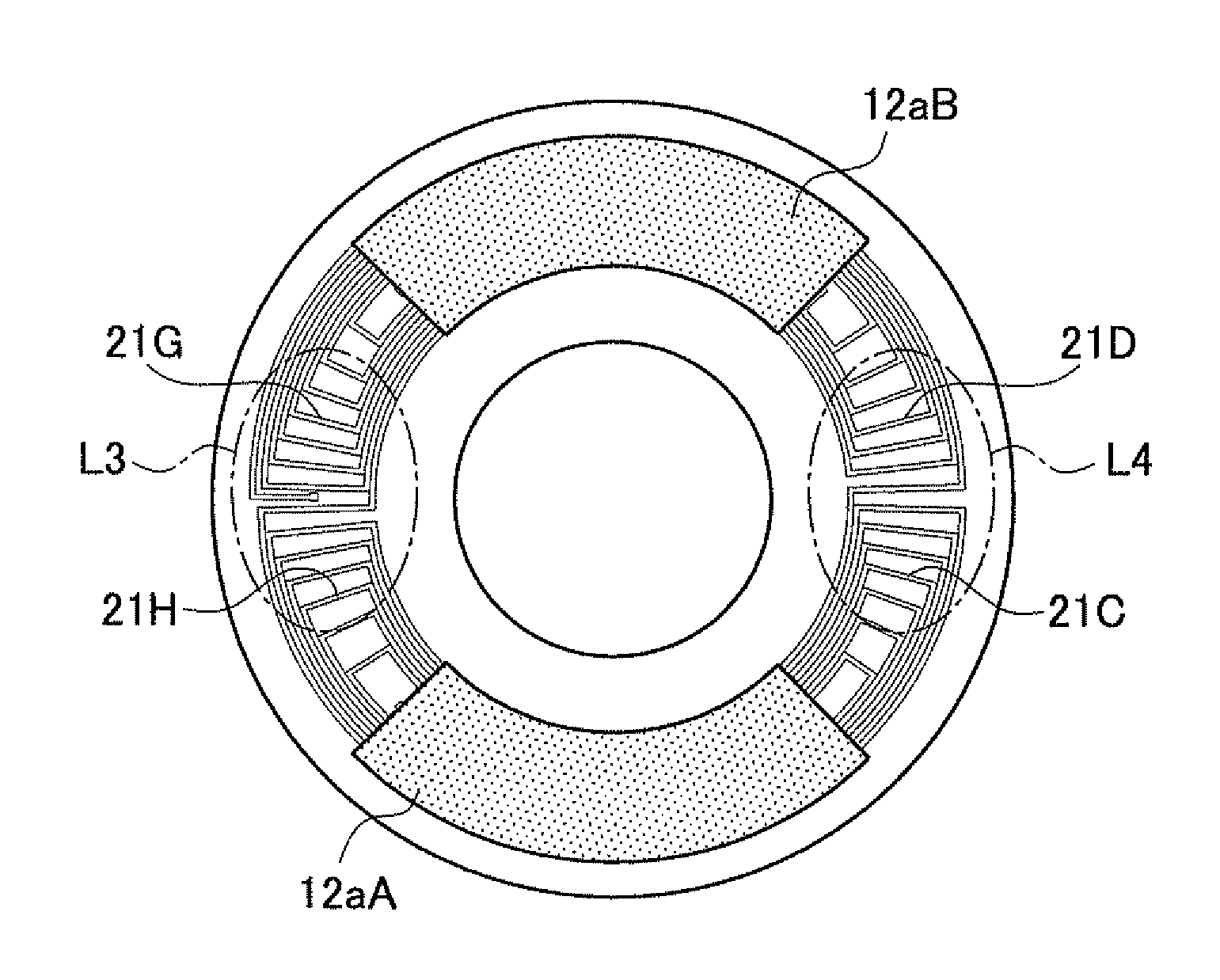
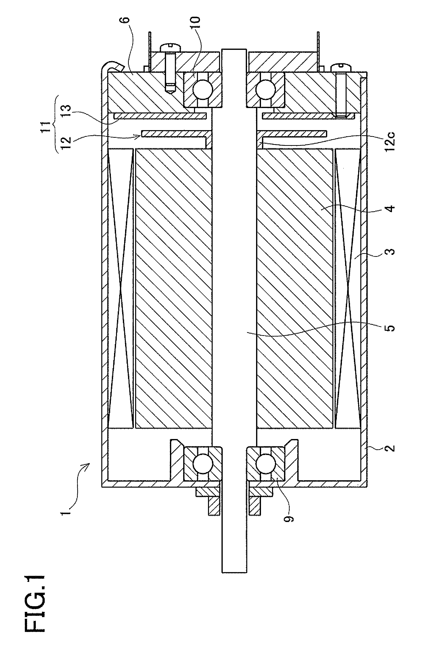
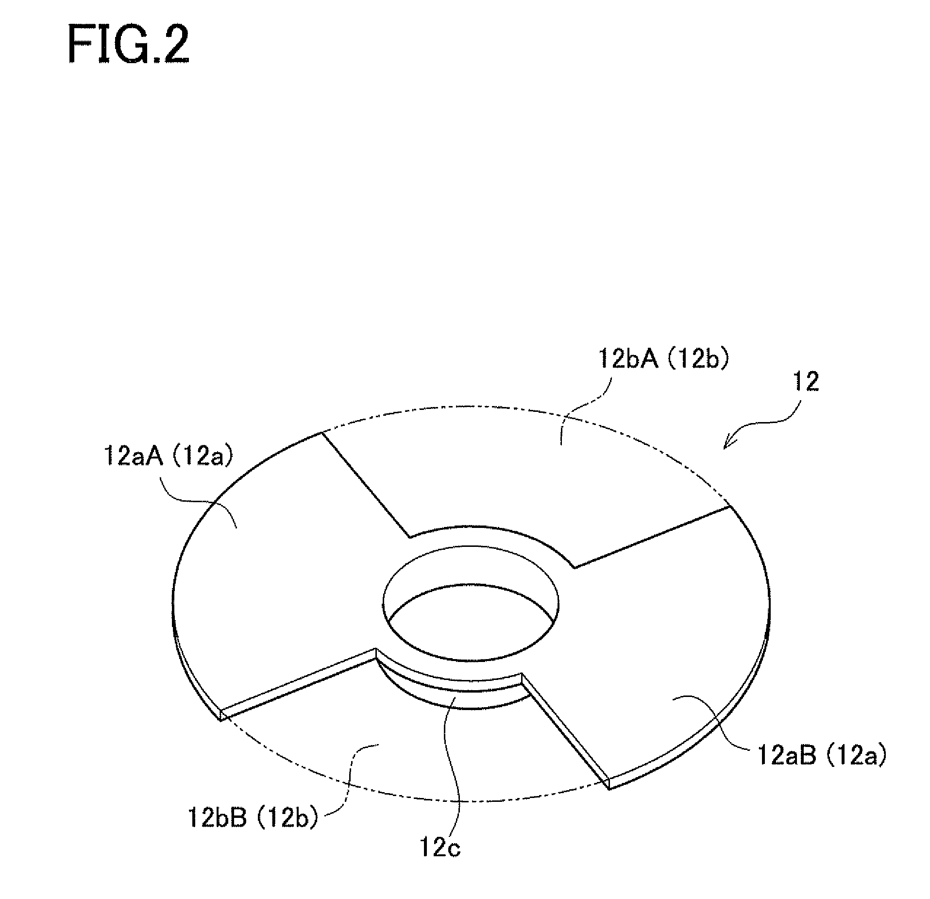
[0215]In a resolver 11 in the third embodiment, a mounting structure thereof is identical to that in FIG. 1 in the first embodiment and its details are not repeated herein. Further, a structure of a resolver rotor 12 is identical to that in FIG. 2 in the first embodiment and its details are not repeated herein. A circuit section 11X is also identical to that in FIG. 3 in the first embodiment and its details are not repeated herein.
[0216]The operations of an excitation coil 123, the resolver rotor 12, a sine wave coil 121, and a cosine wave coil 122 will be explained below. Graphs (a) to (d) in FIG. 29 show the operations and characteristics of the resolver. In FIG. 29, (a) shows a positional relationship between a resolver stator 113 (a stator base flat plate 130, the excitation coil 123, the sine wave coil 121, and the cosine wave coil 122) and the ...
fourth embodiment
[0260]A fourth embodiment of a rotation angle sensor according to the present invention will be explained in detail below referring to accompanying drawings. The following explanation is made so that identical components to those in the third embodiment are given the same reference signs and with a focus on differences from the third embodiment.
[0261]The fourth embodiment differs from the third embodiment in the structure of the resolver stator 113 and in particular in the structures of the excitation coils 124 and 125 and the detection coils 132 and 134. FIG. 38 is an exploded perspective view of the resolver stator 113. FIG. 39 is an exploded, enlarged perspective view of part of the components shown in FIG. 38. FIG. 40 is a perspective view of an exploded, enlarged perspective view of part of the components in FIG. 38.
[0262]As shown in FIG. 38, the resolver stator 113 includes a base flat plate 130, an insulating layer 131, a first excitation coil 124, an insulating layer 136, a ...
PUM
 Abstract
Description
Claims
Application Information
 - R&D
- Intellectual Property
- Life Sciences
- Materials
- Tech Scout
- Unparalleled Data Quality
- Higher Quality Content
- 60% Fewer Hallucinations
Browse by: Latest US Patents, China's latest patents, Technical Efficacy Thesaurus, Application Domain, Technology Topic, Popular Technical Reports.
© 2025 PatSnap. All rights reserved.Legal|Privacy policy|Modern Slavery Act Transparency Statement|Sitemap|About US| Contact US: help@patsnap.com


