Backlight assembly for supplying electric power to a light-emitting element via a connector and a backlight unit and a liquid crystal display which use the backlight assembly

a backlight assembly and light-emitting element technology, which is applied in the field of backlight assembly for a display apparatus and a backlight unit and a liquid crystal display apparatus, can solve the problems of increasing man-hours, difficult to further reduce the number of parts required for the backlight assembly, and significantly worsening workability, so as to reduce the number of parts and cost

Active Publication Date: 2014-05-20
JAPAN AVIATION ELECTRONICS IND LTD
View PDF16 Cites 2 Cited by
  • Summary
  • Abstract
  • Description
  • Claims
  • Application Information

AI Technical Summary

Benefits of technology

[0016]In the above structure, the substrates (the light-emitting element substrates 123a-123f and the power supply substrate 237) on the front and rear faces of the chassis are connected to each other with the connectors by passing the harness through the hole of the chassis. However, such a structure inevitably requires the rubber plug 231, the light-emitting element connectors 133, the power supply substrate connectors 235, and the harness 233 having the connectors on both sides thereof. Accordingly, it is difficult to further reduce the number of parts required for the backlight assembly and thus to achieve cost reduction.
[0017]Furthermore, when the backlight assembly is assembled, the above structure requires a process of passing the harness through the hole of the chassis and connecting the harness to the substrates on the front and rear faces of the chassis. For a structure in which components are assembled by stacking, such as a backlight unit of a liquid crystal display device, a process of passing a harness through a hole considerably worsens the workability and increases the man-hour. As a result, the manufacturing cost is problematically increased.
[0018]Moreover, some liquid crystal display devices use the same harness and light-emitting element substrates and use different power supply substrates depending upon the characteristics of the liquid crystal display devices. With the aforementioned structure, connectors corresponding to the connectors of the harness should be mounted on the power supply substrate irrespective of the kind of the power supply substrate. Therefore, the flexibility of designing the power supply substrate is reduced, thereby increasing cost.
[0019]It is therefore an exemplary object of the present invention to provide a backlight assembly, which facilitates cost reduction as compared to conventional technology.

Problems solved by technology

Accordingly, it is difficult to further reduce the number of parts required for the backlight assembly and thus to achieve cost reduction.
For a structure in which components are assembled by stacking, such as a backlight unit of a liquid crystal display device, a process of passing a harness through a hole considerably worsens the workability and increases the man-hour.
As a result, the manufacturing cost is problematically increased.
Therefore, the flexibility of designing the power supply substrate is reduced, thereby increasing cost.

Method used


Image

  • Backlight assembly for supplying electric power to a light-emitting element via a connector and a backlight unit and a liquid crystal display which use the backlight assembly
  • Backlight assembly for supplying electric power to a light-emitting element via a connector and a backlight unit and a liquid crystal display which use the backlight assembly
  • Backlight assembly for supplying electric power to a light-emitting element via a connector and a backlight unit and a liquid crystal display which use the backlight assembly

Examples


first embodiment

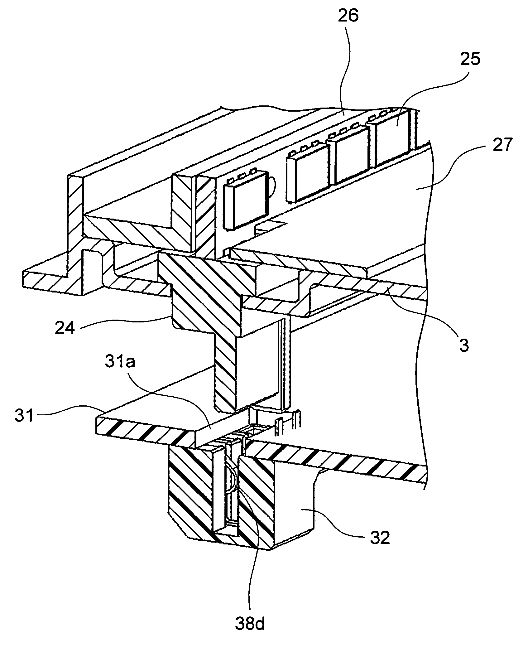
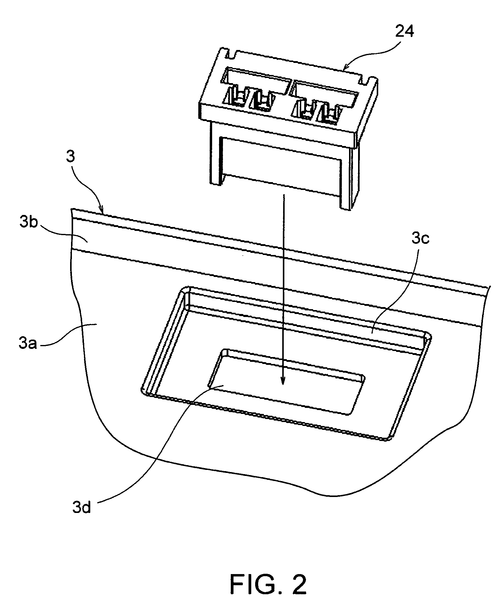
[0079]Next referring to FIGS. 2 to 9, the description will be directed to a backlight assembly according to the present invention and to a method of manufacturing the backlight assembly.

[0080]In FIG. 2, the chassis 3 includes a base plate portion 3a in the form of a rectangular plate and a frame plate portion 3b extending frontward from each side or the vicinity thereof of the base plate portion 3a. The base plate portion 3a has a recessed portion 3c recessed in a front face of the base plate portion 3a. The recessed portion 3c is located near the frame plate portion 3b on one side of the base plate portion 3a. The recessed portion 3c has a bottom with a chassis hole portion 3d formed therein. A first connector 24, which will be described later, is inserted into the chassis hole portion 3d and fixed in the chassis hole portion 3d. FIG. 3 shows a state in which the first connector 24 has been mounted on the chassis 3. The entire chassis 3 on which the first connector 24 has been moun...

second embodiment

[0099]Next, a backlight assembly according to the present invention and a method of manufacturing the backlight assembly will be described below with reference to FIGS. 19 to 30. Portions similar in function to the components of FIGS. 1 to 18 may be denoted by the same reference numbers even if they are different in structure from the components of FIGS. 1 to 18. The explanation of those portions may be omitted from the following description.

[0100]In the backlight assembly according to the first embodiment described with reference to FIGS. 2 to 9, the second connector 32 is mounted on the power supply substrate 31. Nevertheless, the second connector 32 may electrically be connected to the power supply substrate 31 via a flexible harness.

[0101]Furthermore, as shown in FIG. 19, a third connector 42 may be connected to an end opposite to the second connector 32 of the harness 41. The third connector 42 may be mated with and connected to a fourth connector 43 mounted on and connected to...


PUM

PropertyMeasurementUnit
electric poweraaaaaaaaaa
conductivityaaaaaaaaaa
weightaaaaaaaaaa

Abstract

A light-emitting element substrate mounting light-emitting elements is arranged on a front face of a chassis. The light-emitting element substrate is connected to a first connector. A power supply substrate for supplying electric power to the light-emitting element substrate is arranged on a rear face of the chassis. A second connector is connected to the power supply substrate. In addition, the first and the second connectors are connected to each other, so that the power supply substrate supplies electric power to the light-emitting element substrate via the first connector and the second connector. The second connector may electrically be connected to the power supply substrate via a harness.

Description

[0001]This application is based upon and claims the benefit of priority from Japanese patent application Nos. 2010-144566, filed on Jun. 25, 2010 and 2010-283082, filed on Dec. 20, 2010, the disclosures of which are incorporated herein in their entirely by reference.TECHNICAL FIELD[0002]The present invention relates to a backlight assembly for a display apparatus and to a backlight unit and a liquid crystal display apparatus which use the backlight assembly.BACKGROUND ART[0003]Display devices using liquid crystals are widely used for portable devices, computers, wide-screen televisions, and the like because they are lighter in weight, are thinner, and consume less electric power as compared to conventional display devices such as a cathode ray tube. Liquid crystals do not emit light by themselves. Therefore, a backlight unit may be used for emitting light from behind liquid crystals to display a screen on a display device. Generally, a backlight unit includes a backlight assembly ha...

Claims


Application Information

Patent Timeline
Patent Type & Authority Patents(United States)
IPC IPC(8): F21S2/00F21V23/00G02F1/13357
CPCG02F1/133608G02F2001/133612G02F1/133603G02F1/133612G02F1/1333G02F1/1335G02F1/1345
Inventor NAITO, TAKEHARU
Owner JAPAN AVIATION ELECTRONICS IND LTD
Why Eureka
Try Eureka