Automated roof identification systems and methods

a roof identification and automatic technology, applied in the field of automatic roof identification systems and methods, can solve the problems of time-consuming and laborious removal of the owner or key person on the current job site, and the prohibitive time for travel and the cost of commuting

Active Publication Date: 2014-05-20
EAGLEVIEW TECH
View PDF80 Cites 94 Cited by
  • Summary
  • Abstract
  • Description
  • Claims
  • Application Information

AI Technical Summary

Benefits of technology

[0010]In another embodiment, a method for automatically detecting a roof in an image of a building having a roof is provided. The method includes inputting to the associative network statistical measures computed for sections of the first image. The method also includes receiving from the associative network indications of whether a roof is shown in the sections of the first image. The method further includes determining, based on the indicat

Problems solved by technology

If an estimate is needed suddenly at a distant location, the time for travel and the cost of commuting can be prohibitive.
If t

Method used


Image

  • Automated roof identification systems and methods
  • Automated roof identification systems and methods
  • Automated roof identification systems and methods

Examples


first embodiment

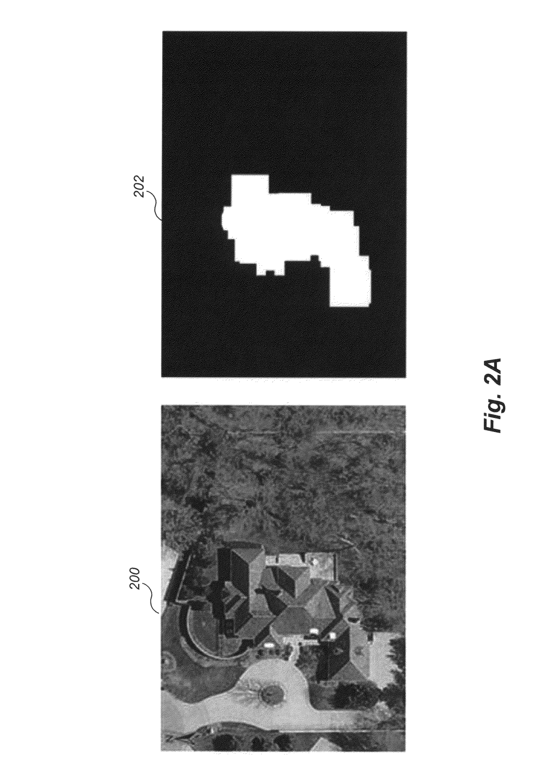
[0046]FIGS. 2A-2D illustrate data sources and process sampling employed in a first embodiment trained on multiple historical images. In this embodiment, historical data including multiple images having known roof areas are used. The roof areas may be known in various ways, such as via previous human and / or machine analysis.

[0047]FIGS. 2A and 2B illustrate example historical data. In particular, FIG. 2A illustrates an example image 200 and a corresponding mask 202. FIG. 2B illustrates another example image 204 and a corresponding mask 206. The masks 202 and 206 indicate (in white) which sections of the image are roof areas and indicate (in black) which sections of the image are non-roof areas.

[0048]FIGS. 2C and 2D illustrate sampling techniques used during the determination of image measures. As part of the training process used in the first embodiment, each of the historical images is processed by determining, for each pixel in the image, one or more measures within a moving (N×M) s...

second embodiment

[0050]FIG. 2F illustrates example image measures (features) used during training. The image measures can be broadly classified into localized measures and neighborhood measures. Localized measures describe image textural characteristics at a particular processing point (e.g., a pixel at the center of one of the N×M sampling windows described above). Example localized measures may include surface fractal analysis, wavelet coefficients, and topological contour complexity variation (TCCV). Neighborhood measures include ranging related neighborhood measures that describe the organization of structure surrounding a particular processing point. Example neighborhood measures include radial complexity and radial organization variation. FIG. 2F depicts neural networks 230a-230e that are trained based on image measures or separable descriptor groups derived from image measures determined as described above for either the first or Each of the neural networks 230a-230e is a full associative n-...


PUM


Abstract

Automatic roof identification systems and methods are described. Example embodiments include a roof estimation system configured to automatically detect a roof in a target image of a building having a roof. In one embodiment, automatically detecting a roof in a target image includes training one or more artificial intelligence systems to identify likely roof sections of an image. The artificial intelligence systems are trained on historical image data or an operator-specified region of interest within the target image. Then, a likely outline of the roof in the target image can be determined based on the trained artificial intelligence systems. The likely roof outline can be used to generate a roof estimate report. This abstract is provided to comply with rules requiring an abstract, and it is submitted with the intention that it will not be used to interpret or limit the scope or meaning of the claims.

Description

CROSS REFERENCE TO RELATED APPLICATIONS[0001]This application claims the benefit of U.S. Provisional Patent Application No. 61 / 197,895, entitled “AUTOMATED TECHNIQUES FOR ROOF ESTIMATION,” filed Oct. 31, 2008, which is incorporated herein by reference in its entirety.BACKGROUND[0002]1. Field of the Invention[0003]This invention relates to automated systems and methods for estimating construction projects, and more particularly, to such systems and methods for automatically identifying a roof in an image of a building having a roof.[0004]2. Description of the Related Art[0005]Homeowners typically ask several roofing contractors to provide written estimates to repair or replace a roof on a house. Heretofore, the homeowners would make an appointment with each roofing contractor to visit the house to determine the style of roof, take measurements, and to inspect the area around the house for access and cleanup. Using this information, the roofing contractor then prepares a written estim...

Claims


Application Information

Patent Timeline
IPC IPC(8): G06K9/00G06V10/34
CPCG06K9/00624G06K9/00637G06K9/44G06K9/4604G06K9/6203G06K9/6271G06K9/66G06V20/176G06V10/34G06V10/7515G06V30/19173G06F18/24133
Inventor CIARCIA, CHRISTOPHER ALBERTPERSHING, CHRIS
Owner EAGLEVIEW TECH
Why Eureka
Try Eureka